Parameter data records
B.2 Structure of a data record for input channels of the analog on-board I/O
CPU 1512C-1 PN (6ES7512-1CK01-0AB0)
Manual, 12/2017, A5E40898741-AA
169
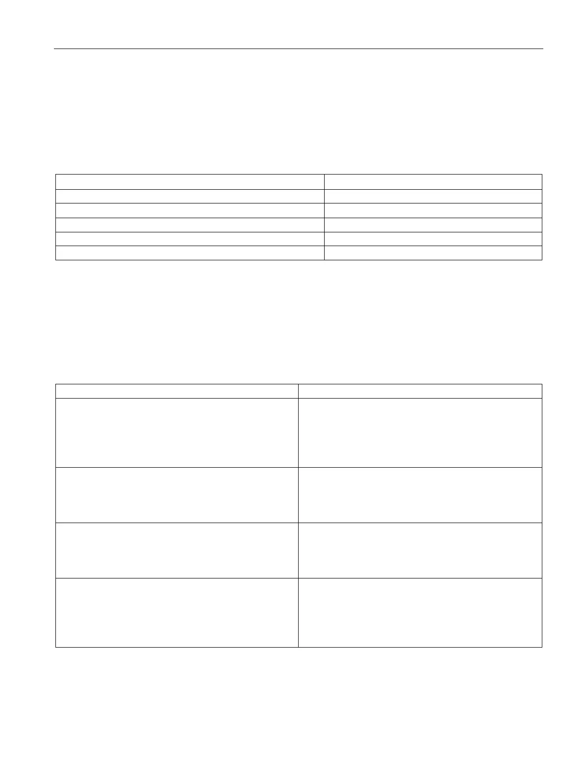
Codes for measurement types
The following table contains all measurement types of the inputs of the analog on-board I/O
with the corresponding codes. You must enter these codes in byte 2 of the data record for
the corresponding channel (refer to the figure Structure of data record 0: Bytes 0 to 6).
Table B- 1 Codes for measurement type
Voltage (valid for channels 0 to 3) 0000 0001
Current, 4-wire measuring transducer (valid for channels 0 to 3)
Resistance (valid for channel 4) 0000 0100
Thermal resistor linear (valid for channel 4)
Codes for measuring ranges
The following table contains all measuring ranges of the inputs of the analog on-board I/O
with the corresponding codes. You must enter these codes in each case in byte 3 of the data
record for the corresponding channel (refer to the figure Structure of data record 0: Bytes 0
to 6).
Table B- 2 Codes for measuring range
±5 V
±10 V
1 to 5 V
0000 1000
0000 1001
0000 1010
Current, 4-wire measuring transducer
0 to 20 mA
4 to 20 mA
0000 0010
0000 0011
150 Ω
300 Ω
0000 0001
0000 0010
Pt 100 Climate
Ni 100 Climate
Pt 100 Standard
Ni 100 Standard
0000 0000
0000 0001
0000 0010
0000 0011

 Loading...


