Technology functions
3.2 Pulse generators
CPU 1512C-1 PN (6ES7512-1CK01-0AB0)
Manual, 12/2017, A5E40898741-AA
59
For the frequency output mode, the user program directly accesses the control and feedback
interface of the channel.
A reconfiguration via the instructions WRREC/RDREC and parameter assignment data
record 128 is supported. You can find additional information in section Parameter data
records (PWM) (Page 187).
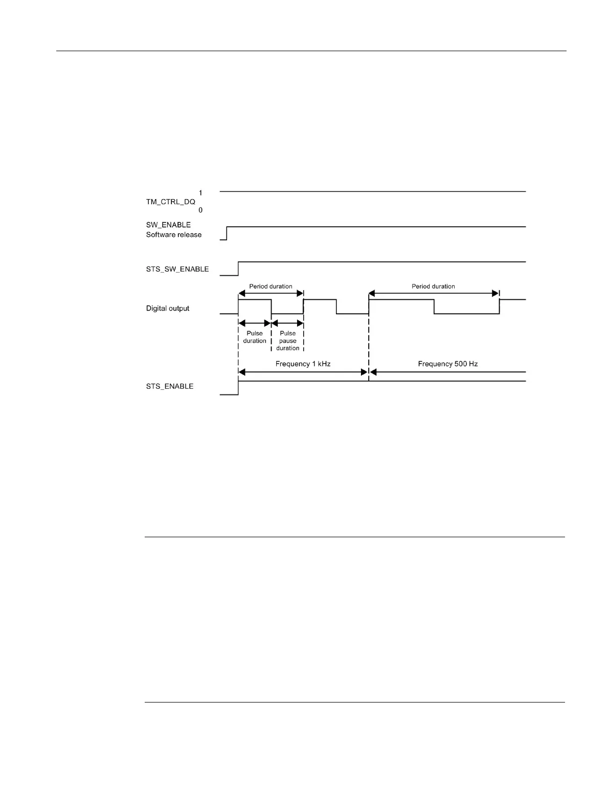
Figure 3-3 Pulse schematic
Starting the output sequence
The control program must initiate the enable for the output sequence with the help of the
software enable (SW_ENABLE 0 → 1). The feedback bit STS_SW_ENABLE indicates that
the software enable is pending at the pulse generator.
If the software enable is activated (rising edge), STS_ENABLE is set. The output sequence
runs continuously, as long as SW_ENABLE is set.
Note
Output control signal TM_CTRL_DQ
•
If TM_CTRL_DQ = 1, the technology function takes over the control and generates pulse
sequences at the output PWM DQA.
If TM_CTRL_DQ = 0, the user program takes over the control and the user can directly
set the output PWM DQA via the control bit SET_DQA.
Canceling the output sequence
Deactivating the software enable (SW_ENABLE
= 1 → 0) during the frequency output
cancels the current output sequence. The last cycle duration is not completed.
STS_ENABLE and the digital output PWM
DQA are immediately reset to 0.
A renewed pulse output is only possible after a restart of the output sequ
ence.

 Loading...


