Wiring
4.3 Terminal and block diagrams
CPU 1512C-1 PN (6ES7512-1CK01-0AB0)
84 Manual, 12/2017, A5E40898741-AA
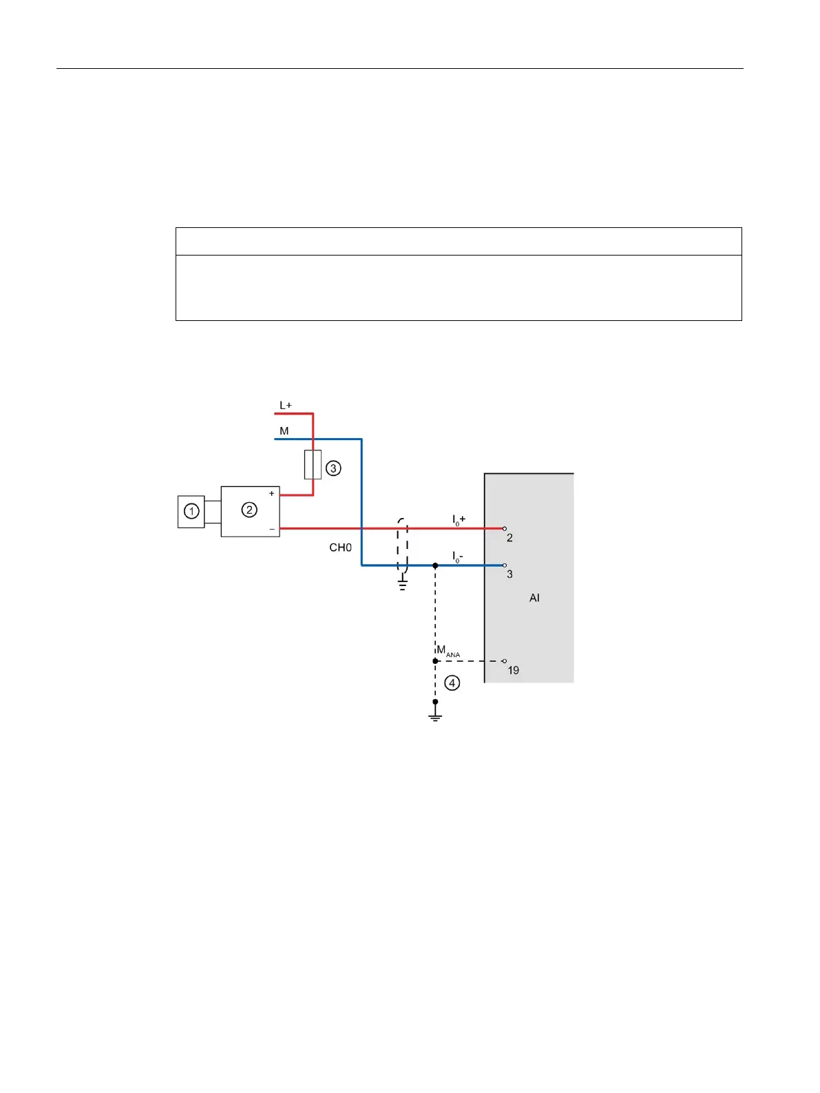
Wiring: 2-wire measuring transducer for current measurement
Alternatively to connecting a 4-wire transducer, you can also connect 2-wire transducers to
channels 0 to 3. An external 24 V power supply is required to connect a 2-wire transducer to
the analog on-board I/O of the compact CPU. Feed this voltage short-circuit proof to the 2-
wire transducer. Use a fuse to protect the power supply unit.
Note that the analog input of the transducer is not protected against destruction in the event
of a defect (short circuit). Take the necessary precautions against such cases.
The figure below shows an example of the connection of a 2-wire transducer to channel 0
(CH0) of the analog on-board I/O.
Sensor (e.g. pressure gauge)
Equipotential bonding cable (optional)
Figure 4-6 2-wire transducer at channel 0
Use the measurement type "Current (4-wire transducer)" and the measuring range
4 to 20 mA for the parameter assignment of the 2 wire transducer in STEP 7 (TIA Portal).

 Loading...


