Wiring
4.3 Terminal and block diagrams
CPU 1512C-1 PN (6ES7512-1CK01-0AB0)
Manual, 12/2017, A5E40898741-AA
87
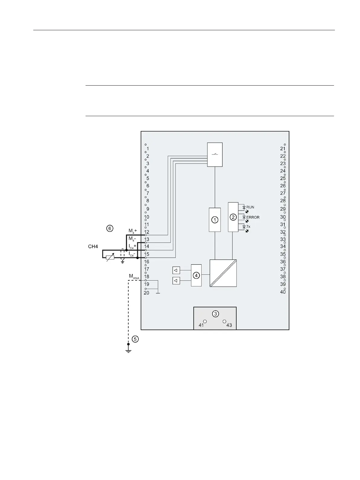
Wiring: 2-wire connection of resistance-type sensors or thermal resistors (RTD)
The following figure shows the terminal assignment for 2-wire connection of resistance-type
sensors or thermal resistors at the channel available for this (channel 4).
Note
2-wire connection
Note that line resistances are not compensated with a 2
-wire connection.
Analog-to-digital converter (ADC)
Infeed element (for shielding only)
Digital-to-analog converter (DAC)
Equipotential bonding cable (optional)
Figure 4-9 Block diagram and terminal assignment for 2-wire connection

 Loading...


