Wiring
4.3 Terminal and block diagrams
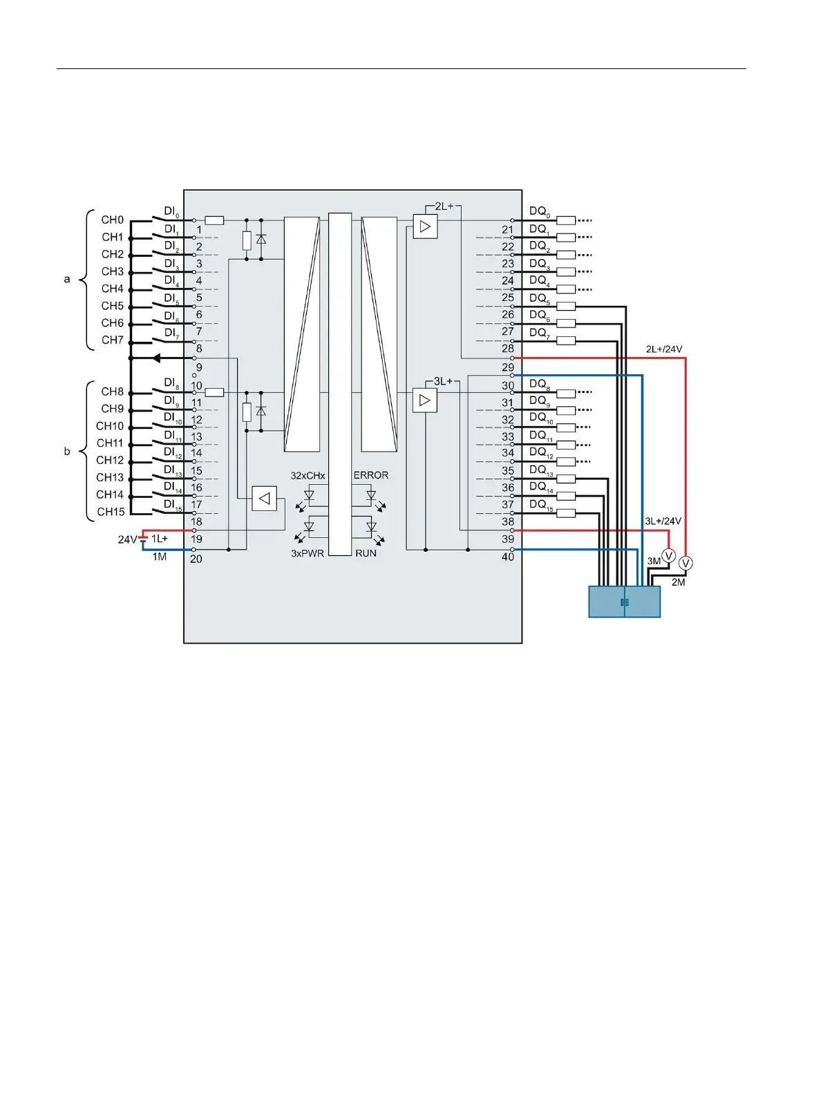
CPU 1512C-1 PN (6ES7512-1CK01-0AB0)
94 Manual, 12/2017, A5E40898741-AA
As a supplement to the block diagram and terminal assignment, the following figure shows
the correct wiring of the outputs in order to prevent switching of the outputs in the event of a
ground wire break.
Figure 4-14 Correct wiring using the digital on-board I/O X11 as an example
The ground is supplied with a first cable from the central terminal block to terminal 30 of the
module and additionally with a second cable also from the central terminal block to
terminal 40 of the module.
At the digital outputs, each of the ground connections of the loads is connected with a
separate cable for each load to the central terminal block.

 Loading...


