EasyManuals Logo

Siemens Simatic S7-1500 CPU 1512C-1 PN User Manual

Siemens Simatic S7-1500 CPU 1512C-1 PN
206 pages
To Next Page IconTo Next Page
To Previous Page IconTo Previous Page
Page #99 background imageLoading...
Page #99 background image
Wiring
4.3 Terminal and block diagrams
CPU 1512C-1 PN (6ES7512-1CK01-0AB0)
Manual, 12/2017, A5E40898741-AA
99
Faulty wiring
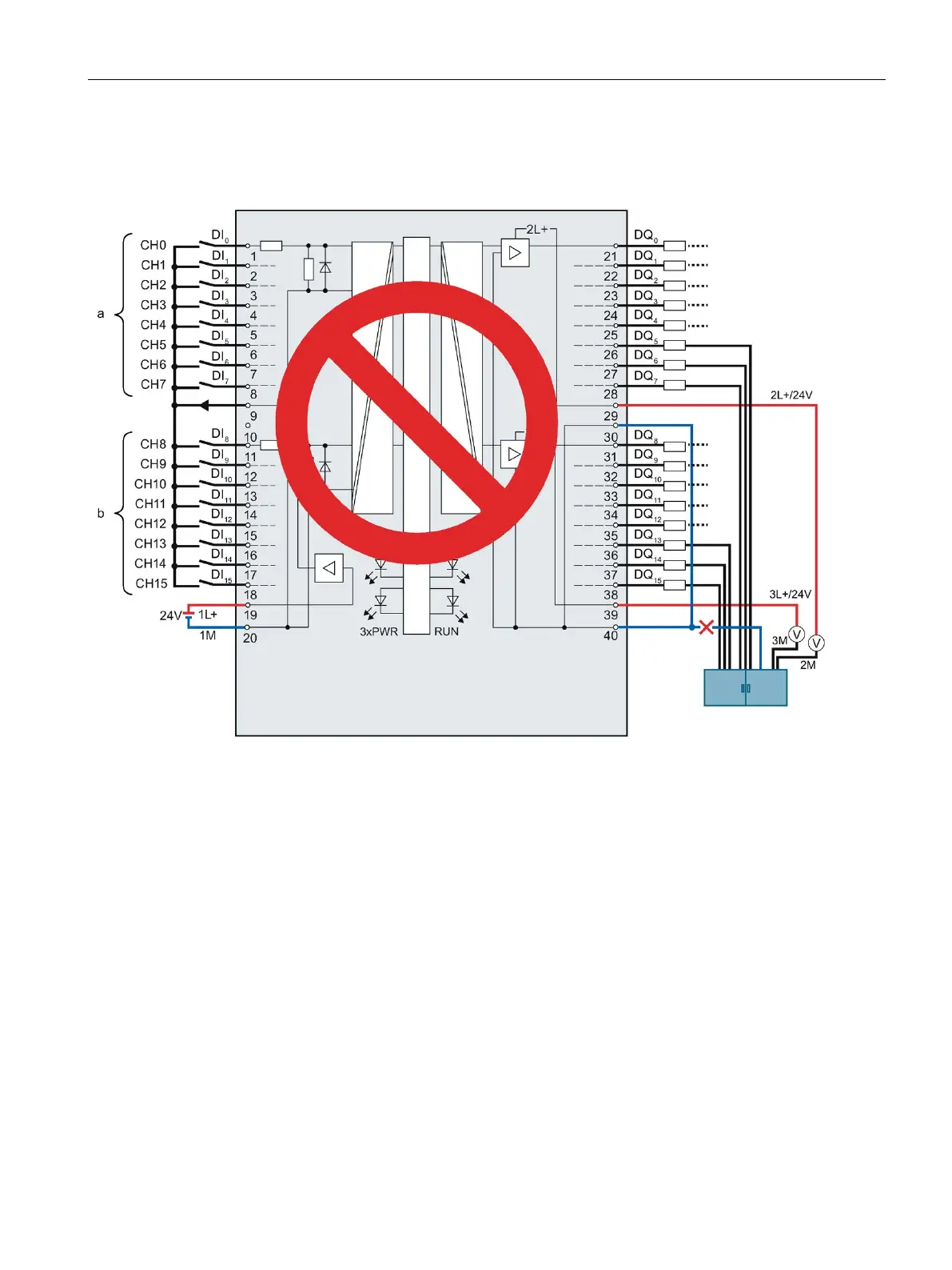
The following figure shows faulty wiring, which has a bridge on the front connector.
Figure 4-19 Faulty wiring using the digital on-board I/O X11 as an example: Bridge
Terminals 30 and 40 are connected in the front connector and only routed with one cable to
the central terminal block. If this cable breaks, terminals 30 and 40 are no longer connected
to the ground. The module's supply current flows out via the output terminal.

Table of Contents

Questions and Answers:

Question and Answer IconNeed help?

Do you have a question about the Siemens Simatic S7-1500 CPU 1512C-1 PN and is the answer not in the manual?

Siemens Simatic S7-1500 CPU 1512C-1 PN Specifications

General IconGeneral
Integrated InterfacesPROFINET
Data Memory1 MB
Number of Signal Boards1
Firmware VersionV2.8
Rated Value (DC)24 V
Number of PROFINET Ports2
Number of PROFINET Ports with Switch2
Integrated Web ServerYes
Number of Digital Inputs16
Number of Digital Outputs16
Number of Analog Outputs2
Number of High-speed Counters6
Program Memory300 KB
Number of Signal Modules32
Engineering withSTEP 7 Professional V13
Interface TypeEthernet
Data StorageYes
Operating Temperature0 to 60 °C
Dimensions147 mm x 129 mm

Related product manuals