EasyManuals Logo

Siemens Simatic S7-1500 CPU 1512C-1 PN User Manual

Siemens Simatic S7-1500 CPU 1512C-1 PN
206 pages
To Next Page IconTo Next Page
To Previous Page IconTo Previous Page
Page #100 background imageLoading...
Page #100 background image
Wiring
4.3 Terminal and block diagrams
CPU 1512C-1 PN (6ES7512-1CK01-0AB0)
100 Manual, 12/2017, A5E40898741-AA
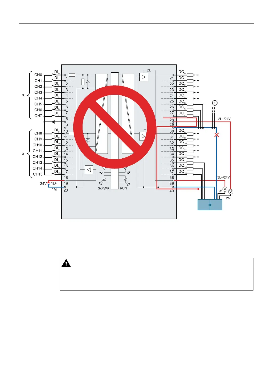
The figure below shows the current flow when the ground connections of the loads and the
ground connection of terminal 30 are routed with a common cable to the central terminal
block.
Ground connections of other plant parts that can also carry large currents.
Figure 4-20 Faulty wiring using the digital on-board I/O X11 as an example: Common cable
If a break occurs in the common cable, the current of the outputs flows via terminal 30 to the
module and via terminal 40 to the central terminal block. The current flows via the module.
WARNING
Current flow with faulty wiring
If a break occurs in the common cable, the current can be very high, depending on the
plant, and lead to the destruction of the module.

Table of Contents

Questions and Answers:

Question and Answer IconNeed help?

Do you have a question about the Siemens Simatic S7-1500 CPU 1512C-1 PN and is the answer not in the manual?

Siemens Simatic S7-1500 CPU 1512C-1 PN Specifications

General IconGeneral
Integrated InterfacesPROFINET
Data Memory1 MB
Number of Signal Boards1
Firmware VersionV2.8
Rated Value (DC)24 V
Number of PROFINET Ports2
Number of PROFINET Ports with Switch2
Integrated Web ServerYes
Number of Digital Inputs16
Number of Digital Outputs16
Number of Analog Outputs2
Number of High-speed Counters6
Program Memory300 KB
Number of Signal Modules32
Engineering withSTEP 7 Professional V13
Interface TypeEthernet
Data StorageYes
Operating Temperature0 to 60 °C
Dimensions147 mm x 129 mm

Related product manuals