CP 341 Point-to-Point Communication, Installation and Parameter Assignment
Manual, 09/2008, A5E02191071-01 111
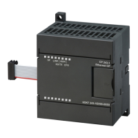
Mounting the CP 341
4
4.1 CP 341 slots
The following section describes the rules you must observe when positioning the CP 341 in
the rack (mounting rail).
Position of the CP 341 in the rack (mounting rail)
The following rules apply when positioning the CP 341 in the rack (mounting rail):
● A maximum of 8 communication modules can be inserted to the right of the CPU.
● The number of communication modules that can be inserted is limited by the
expandability of the CPU (e. g., CPU 312 IFM in first row) or the ET 200M (IM 153) in
distributed applications (single-row configuration only).
Note
Prior to removing or inserting the CP 341, you must switch the CPU to STOP mode and
switch off the power supply. There are no restrictions for removing or inserting the cable
for the integrated interface on the CP 341. However, you must make sure that there is no
data being transmitted via the integrated interface when you do this. Otherwise, data may
be lost.
Further information
Further information about slots is available in the Manual
S7–300 Programmable Controller,
CPU Data, Installation
.
该文档是极速PDF编辑器生成,
如果想去掉该提示,请访问并下载:
http://www.jisupdfeditor.com/

 Loading...


