Product Description
1.2 Design of the CP 341
CP 341 Point-to-Point Communication, Installation and Parameter Assignment
20 Manual, 09/2008, A5E02191071-01
1.2 Design of the CP 341
The CP 341 communication processor is supplied with an integrated serial interface.
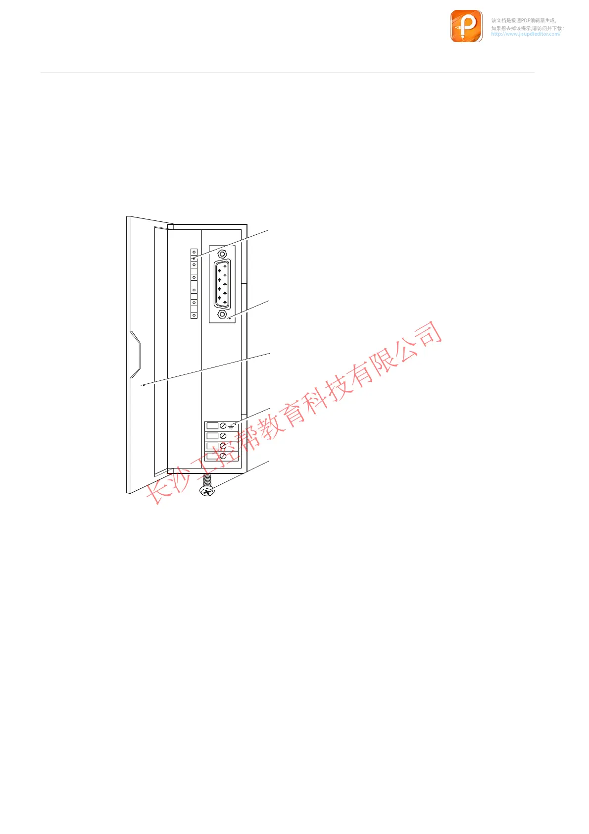
Positions of the module elements
The diagram shows the arrangement of the module elements on the front panel of the
CP 341 communication processor.
6)
7['
5['
0
/
0
,QGLFDWRUV
,QWHJUDWHGLQWHUIDFH
)URQWGRRU
&RQQHFWLRQIRU'&9
VXSSO\
)DVWHQLQJVFUHZ
Figure 1-1 Positions of the module elements on the CP 341 communication processor
LED indicators
The following LED indicators are located on the front panel of the communication processor:
● SF (red) error LED
● TxD (green) interface transmitting
● RxD (green) interface receiving
Section "Diagnostics via the display elements of the CP 341 (Page 186)" describes the
operating states and errors that these LEDs indicate. Section "Subsequent Loading of
Firmware Updates (Page 123)" provides information on the LED indicators that occur when
loading a firmware update.
该文档是极速PDF编辑器生成,
如果想去掉该提示,请访问并下载:
http://www.jisupdfeditor.com/

 Loading...


