Operator controls and indicators
Mode selector switch
The mode selector switch is used to set the current CPU operating mode.
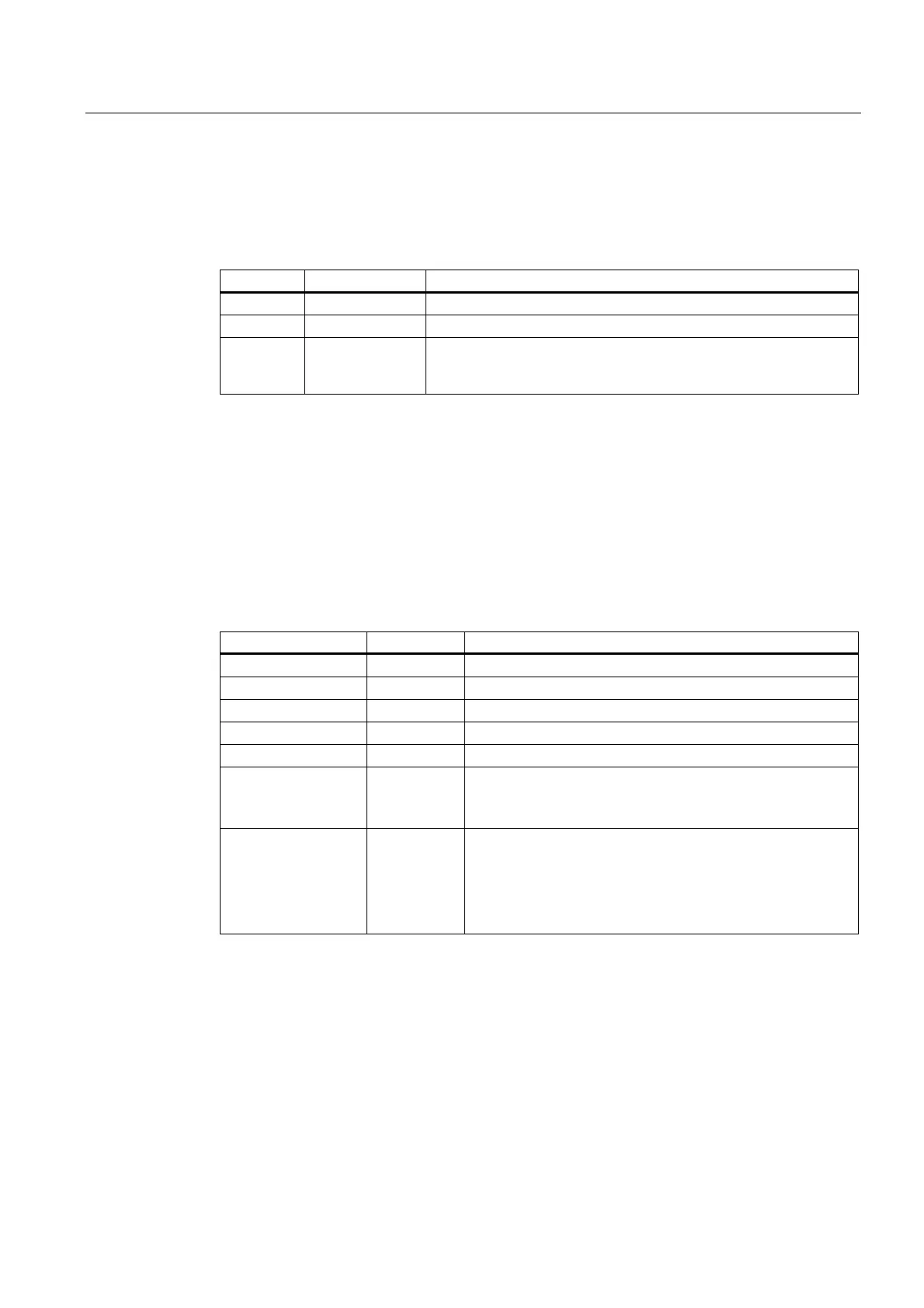
Table 3-3 Switch positions of the mode selector switch
Position Meaning Description
RUN RUN mode The CPU executes the user program.
STOP STOP mode The CPU does not execute a user program.
MRES CPU memory
reset
Mode selector switch position with pushbutton function for CPU
memory reset. A general CPU reset by means of a mode selector
switch requires a specific sequence of operation.
Power supply connection
Each CPU is equipped with a double-pole power supply socket. The connector with screw
terminals is inserted into this socket when the CPU is delivered.
Status and error displays
The CPU is equipped with the following LEDs:
Table 3-4 Status and error displays of the CPU
LED Color Meaning
SF red Hardware or software error
BF1 red Bus errors (MPI/DP)
BF3 red Bus error on DP(DRIVE)
5 VDC green 5V power supply for the CPU and the S7-300 bus
FRCE yellow Active force job
RUN green CPU in RUN
The LED flashes during STARTUP at a rate of 2 Hz, and in
HOLD state at 0.5 Hz.
STOP yellow CPU in STOP, or HOLD, or STARTUP
The LED flashes
• At 0.5 Hz on general reset request
• At 2 Hz during general reset
• At 2 Hz during shutdown (LED RUN lit).
S7-300 CPU Data: CPU 315T-2 DP
Manual, 12/2005, A5E00427933-02
3-3
 Loading...


