Expert Functions
5.6 Measuring Function
Connection of the SINAMICS S120 to the Technology CPU
Product Information, 09/2011, A5E00480378-04
155
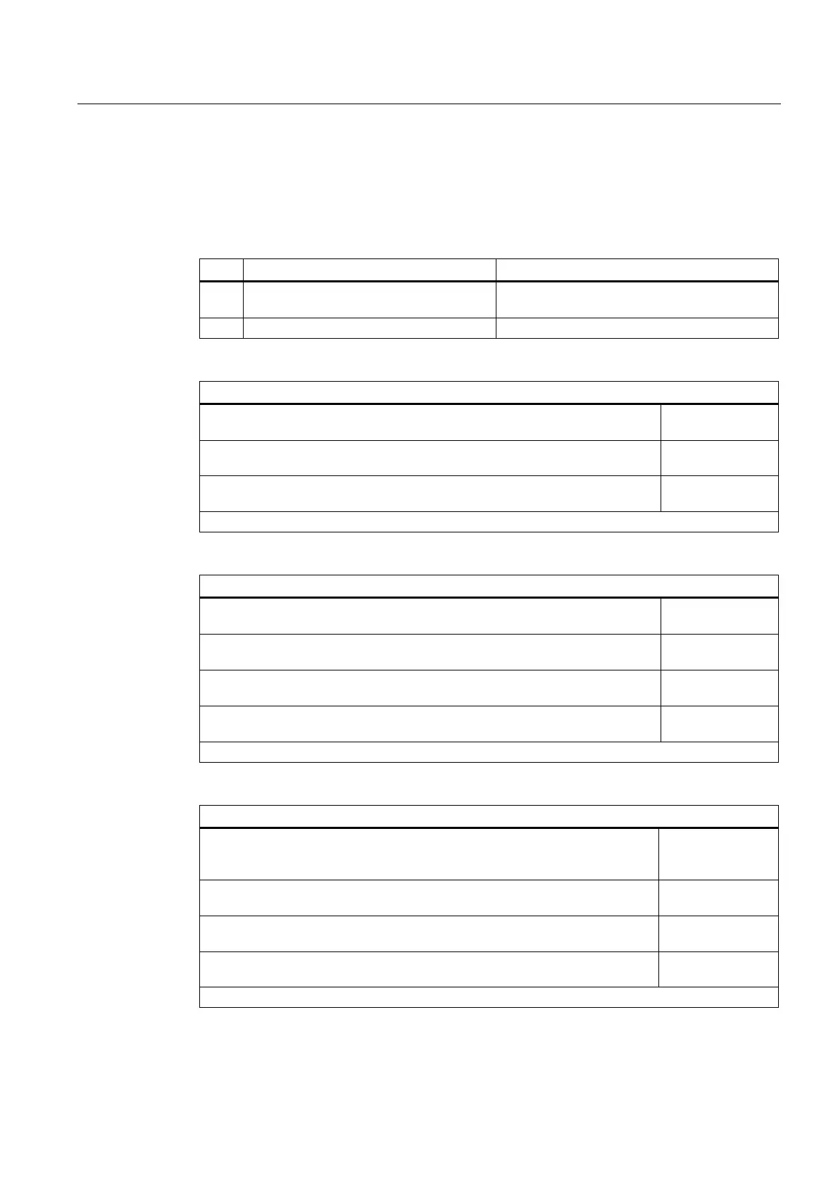
You can determine the response times for your configuration using the following tables.
The values in the tables are based on the set system clocks. By using the actual times,
you can calculate the response time in milliseconds.
The following abbreviations are used in the tables:
Description Supplementary information
IS Interpolator or position-control cycle Can be selected during the configuring of the
measuring input
DP Cycle time on the PROFIBUS DP Can be set in HW Config
Measuring without measuring window
MC_MeasuringInput
-> ready to detect the measuring edge
3 (IS) + 7 (DP)
Detection of the measuring edge
-> result in the Technology CPU for further processing
2 (IS) + 10 (DP)
Total
-> minimum time between 2 measurements*)
5 (IS) + 17 (DP)
*) Any system limitations must also be considered.
Measuring with measuring window: Measuring edge is detected in the window
MC_MeasuringInput
-> ready to evaluate the measuring range (start of the measuring window)
2 (IS)
Start of the measuring window on the axis is reached (mechanical)
-> ready to detect the measuring edge
2 (IS) + 7 (DP)
Detection of the measuring edge
-> result in the Technology CPU for further processing
2 (IS) + 10 (DP)
Total
-> minimum time between 2 measurements*)
5 (IS) + 17 (DP)
*) Any system limitations must also be considered.
Measuring with measuring window: No measuring edge in the window
MC_MeasuringInput
-> ready to evaluate the measuring range (start of the
measuring window)
2 (IS)
Start of the measuring window on the axis is reached (mechanical)
-> ready to detect the measuring edge
2 (IS) + 7 (DP)
Start of the measuring window on the axis is reached (mechanical)
-> reset: "Ready to detect the measuring edge"
2 (IS) + 7 (DP)
Total
-> minimum time between 2 measurements*)
7 (IS) + 24 (DP)
*) Any system limitations must also be considered.

 Loading...


