Wiring the S7-400
4-45
S7-400 and M7-400 Programmable Controllers, Installation Manual
C79000-G7076-C424-01
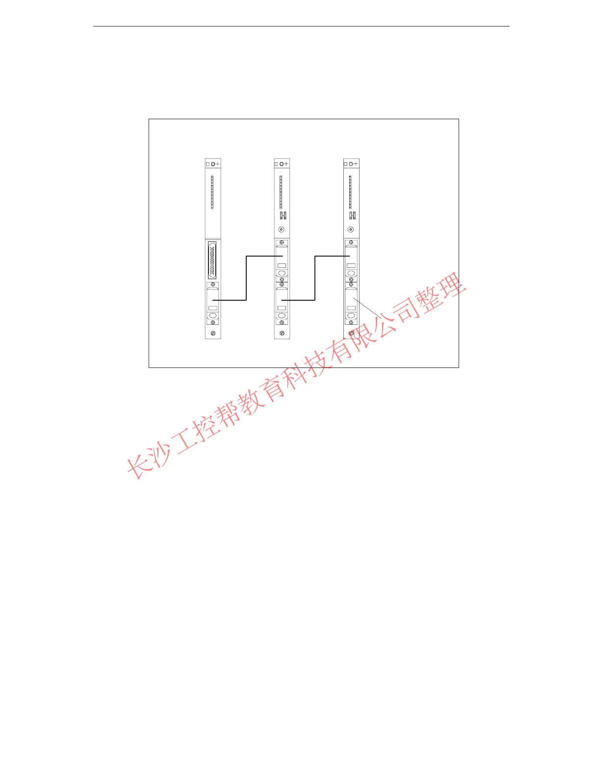
9. Connect the remaining receive IMs by connecting one send interface (lower
female connector X2) to one receive interface (upper male connector X1) in
each case.
Send IM Receive IM Receive IM
Terminator
Figure 4-19 Connection Between a Send IM and Two Receive IMs
10.Plug the terminator into the lower female connector of the receive IM in the last
ER of the chain (see
Reference Manual
, Chapter 7).
www.PLCworld.cn

 Loading...


