Wiring the S7-400
4-44
S7-400 and M7-400 Programmable Controllers, Installation Manual
C79000-G7076-C424-01
4.24 Interconnecting the CR and ER(s)
Interconnecting the Interface Modules
When you assemble a programmable controller comprising a CR and one or more
ERs, you connect the racks via the connecting cables of the interface modules.
To interconnect the interface modules, follow the steps outlined below:
1. Ensure that all the connecting cables needed for the programmable controller
are ready. Allow for the maximum cable lengths permitted for your assembly
(see Chapter 2) and check that you have the correct cables (see
Reference
Manual
, Chapter 7).
2. Start with the send IM (the interface module in the central rack).
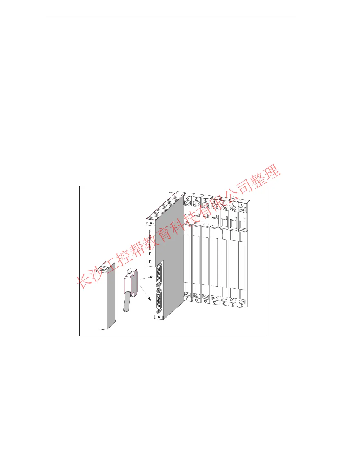
3. Open the cover of the send IM.
4. Plug the male connector of the first connecting cable into one of the female
connectors of the send IM and screw the connector on.
Figure 4-18 Plugging a Connecting Cable into a Send IM
5. If you wish to connect two chains with ERs to this send IM, plug the connector
of the second connecting cable into the other port of the send IM.
6. Close the cover of the send IM.
7. Open the cover of the first receive IM (interface module in the ER).
8. Plug the free end of the connecting cable into the upper male connector
(receive interface) of the receive IM and screw the connector on.
www.PLCworld.cn

 Loading...


