Assembling the M7-400
8-2
S7-400 and M7-400 Programmable Controllers, Installation Manual
C79000-G7076-C424-01
8.1 Mechanical Configuration
Introduction
Explained in this section are the rules you must observe for arranging modules in
the M7-400 automation computer.
All other information which is important for the mechanical configuration applies
both to the S7-400 and the M7-400, and is described in Chapter 2.
Rules for the Arrangement of Modules
You must observe the following rules for the arrangement of modules in a rack:
The power supply module must be inserted in slot 1 in all racks.
The receive IM in the expansion rack must always be inserted on the extreme
right.
A module assembly comprising CPU and expansion units must be configured in
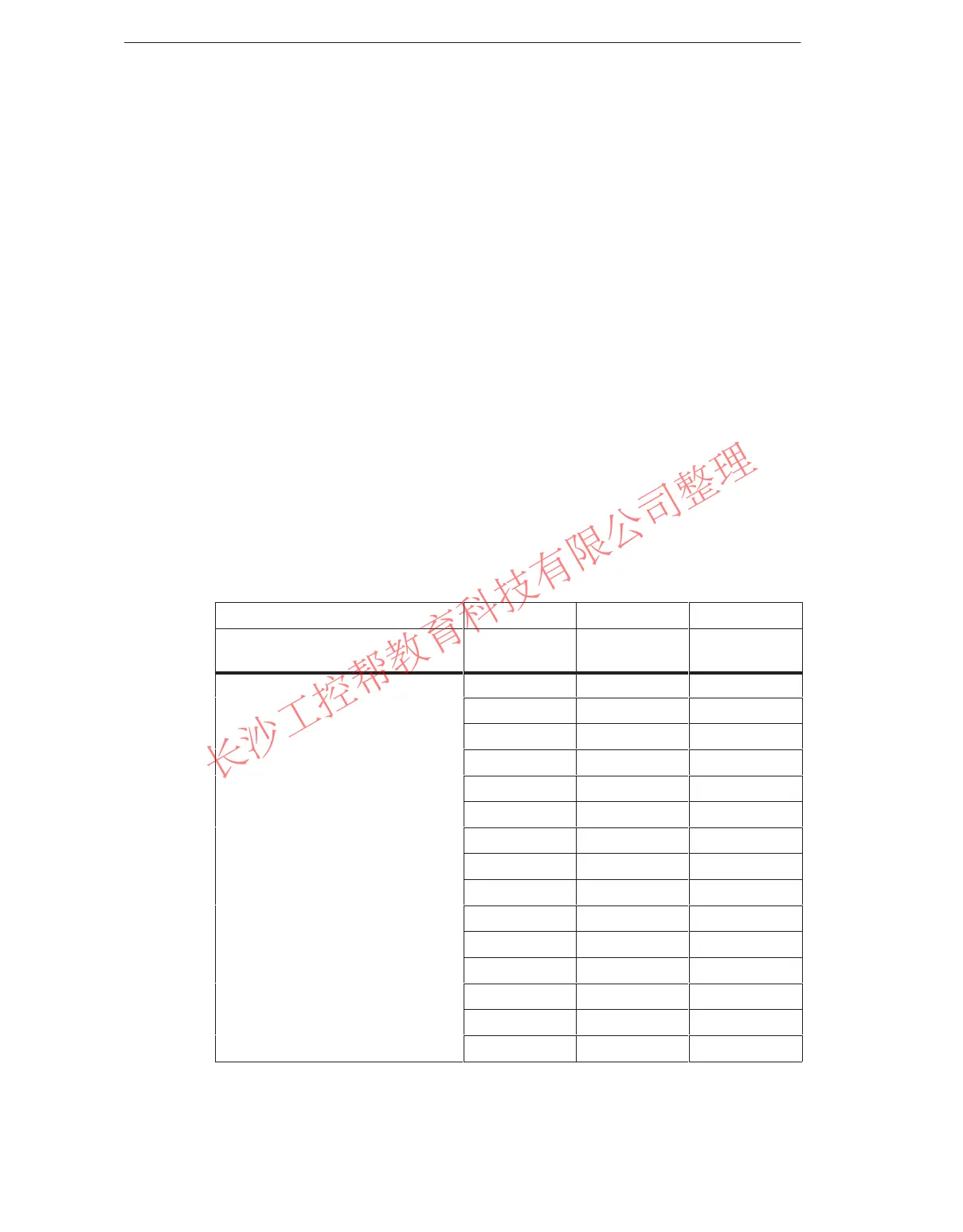
a particular sequence. Shown in Table 8-1 are the possible configurations of a
module assembly with a specified sequence for the expansion units.
Table 8-1 Sequence in the Module Subassembly
CPU
Slot Slot Slot
Slot n and n + 1 for double-width
CPUs
n + 2 n + 3 n + 4
EXM 478 - -
EXM 478 EXM 478 -
EXM 478 EXM 478 EXM 478
EXM 478 EXM 478 ATM 478
EXM 478 ATM 478 ATM 478
EXM 478 ATM 478 -
ATM 478 - -
CPU 486-3, CPU 488-3
ATM 478 ATM 478 -
ATM 478 ATM 478 ATM 478
MSM 478 - -
EXM 478 MSM 478 -
EXM 478 EXM 478 MSM 478
EXM 478 MSM 478 ATM 478
MSM 478 ATM 478 ATM 478
MSM 478 ATM 478 -
www.PLCworld.cn

 Loading...


