Installing the S7-400
2-27
S7-400 and M7-400 Programmable Controllers, Installation Manual
C79000-G7076-C424-01
2.11 Rules for the Arrangement of Modules
Rules for S7-400 and M7-400
Given in this section are the rules you must observe when arranging modules in
the S7-400. The rules for M7-400 modules can be found in Section 8.1
“Mechanical Configuration”.
Arrangement of Modules
You need observe only two rules for the arrangement of modules in a rack:
S In all racks, the power supply module must always be inserted on the extreme
left (beginning with slot 1). In the UR2-H from slot 1 in both segments.
S The receive IM in the ER must always be inserted on the extreme right. In the
UR2-H at slot 9 once per segment.
Note
Establish whether there are additional regulations applying to all modules not
described in this manual.
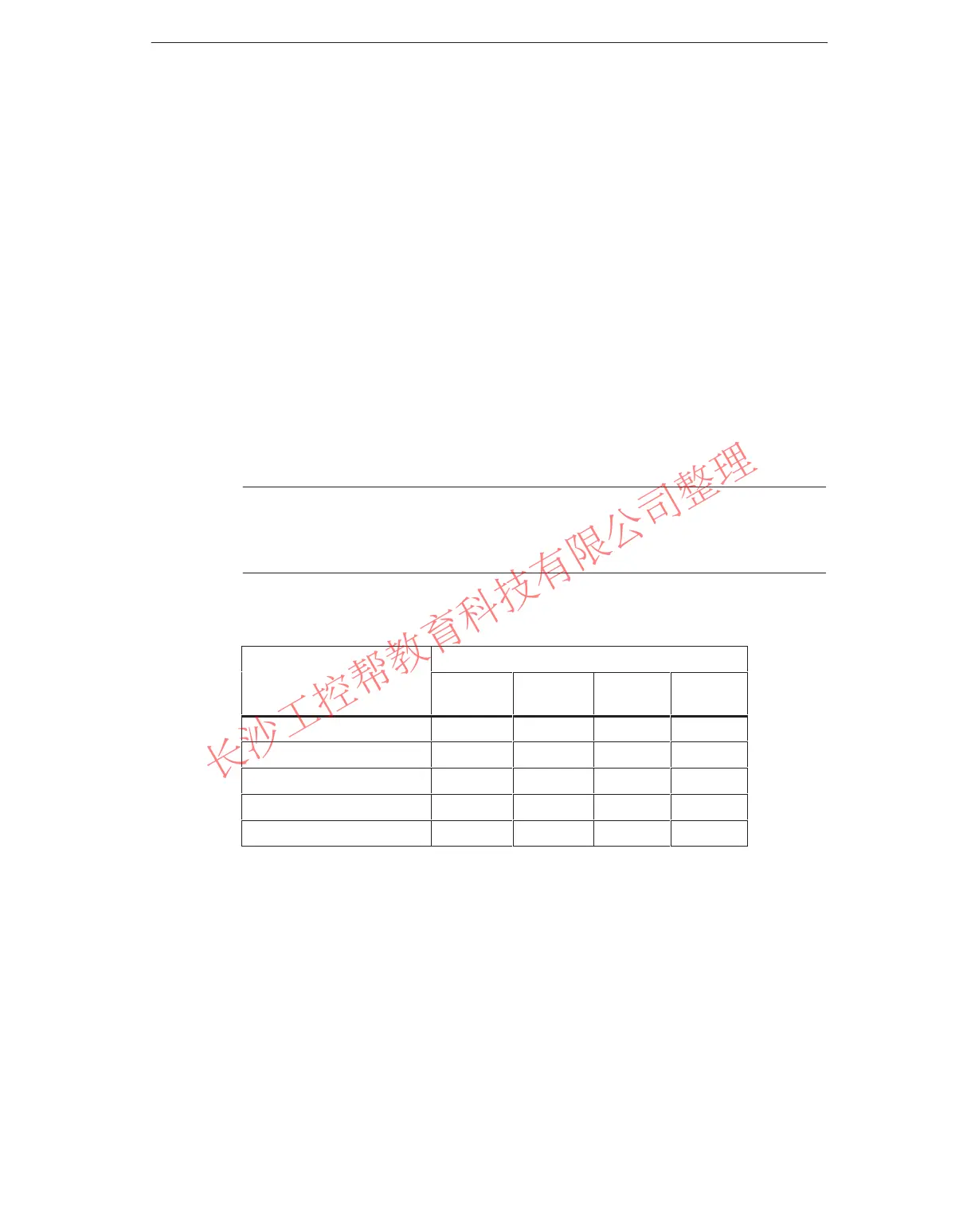
The following table shows which modules can be used in the different racks:
Modules Racks
UR1, UR2
as CR
UR1, UR2
as ER
CR2 ER1, ER2
Power Supply Modules F F F F
CPUs F F
Send IMs F F
Receive IMs F F
Signal Modules F F F F
Space requirement of the racks
In the S7-400 system, there are modules occupying one, two, or three slots (width
25, 50, or 75 mm). Refer to the technical specifications of the module under the
keyword “dimensions” to see how many slots a module occupies.
The mounting depth of a rack fitted with modules is 237 mm maximum.
www.PLCworld.cn

 Loading...


