Wiring the S7-400
4-46
S7-400 and M7-400 Programmable Controllers, Installation Manual
C79000-G7076-C424-01
4.25 Setting the Fan Subassembly to the Line Voltage and Wiring It
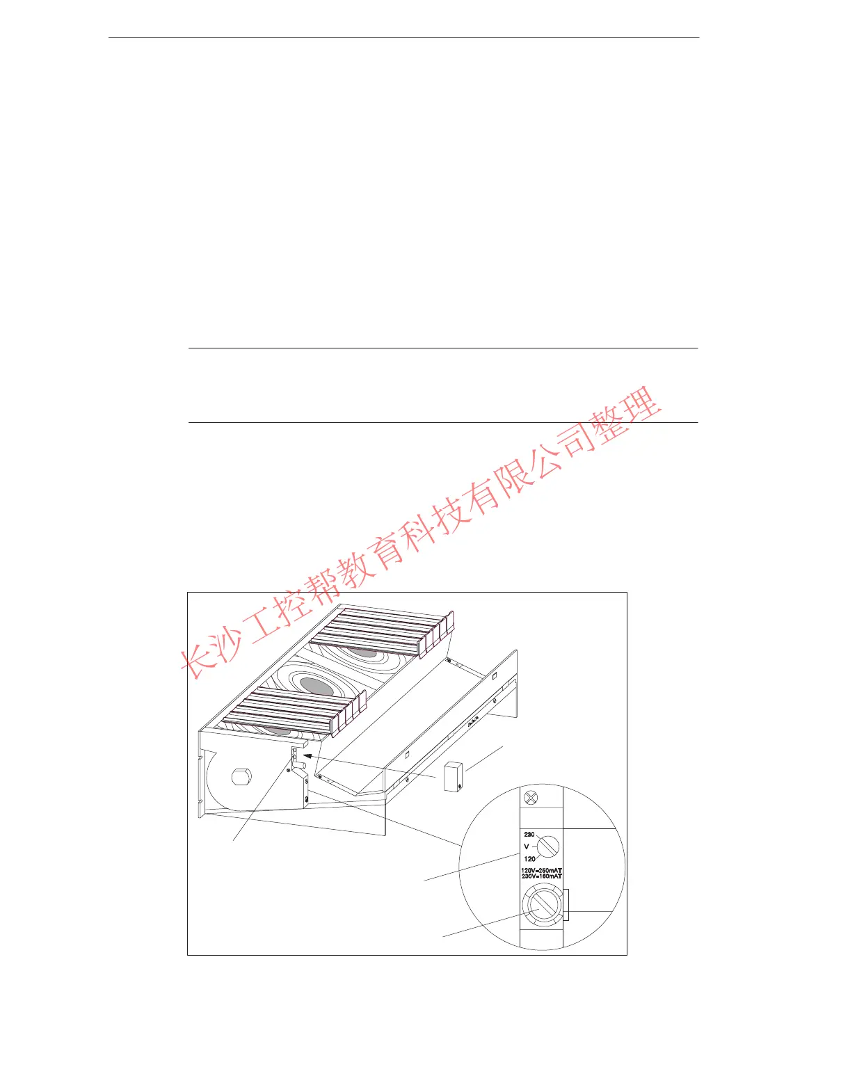
Setting the Fan Subassembly to the Line Voltage
Check whether the voltage selector switch in the fan subassembly is set to your
line voltage (see Figure 4-20).
Fuse
The fan subassembly has two standard fuses:
A 250 mA slow blow fuse for the 120 V range
A 160 mA slow blow fuse for the 230 V range.
The fuse for the 230 V range is fitted before delivery.
Note
If you change the voltage range, you must also fit the fuse for this voltage range in
the fan subassembly. Replacing the fuse is described in Chapter 7.
Wiring the Fan Subassembly
1. Strip the cores of the power cable and press-fit wire end ferrules to the cores.
2. Insert the cores in the power terminals of the fan subassembly. Use a suitable
screwdriver to release the spring contacts of the power terminals.
3. The small cover serves as a strain relief for the power cable. Choose one of the
three sizes provided to suit your cable cross-section.
4. Screw the strain relief on.
Power terminals
(spring contacts)
Voltage selector switch
Fuse cap
Fit the small cover
as a strain relief
Figure 4-20 Wiring the Fan Subassembly
www.PLCworld.cn

 Loading...


