Wiring the S7-400
4-41
S7-400 and M7-400 Programmable Controllers, Installation Manual
C79000-G7076-C424-01
4.23 Fitting the Front Connector
Principle of a Coding Key
To reduce the risk of a wired front connector being plugged into the wrong type of
module after rewiring or module replacement, the signal modules have a coding
key for front connectors.
A coding key comprises two parts: one part is permanently connected to the
module; the second part is still connected to the first part when delivered (see
Figure 4-16).
When you plug in a front connector, the second part of the coding key engages in
the connector, becoming detached from the part connected to the signal module.
Both parts of the coding key are mating elements and a front connector with the
wrong mating element cannot be plugged into this signal module.
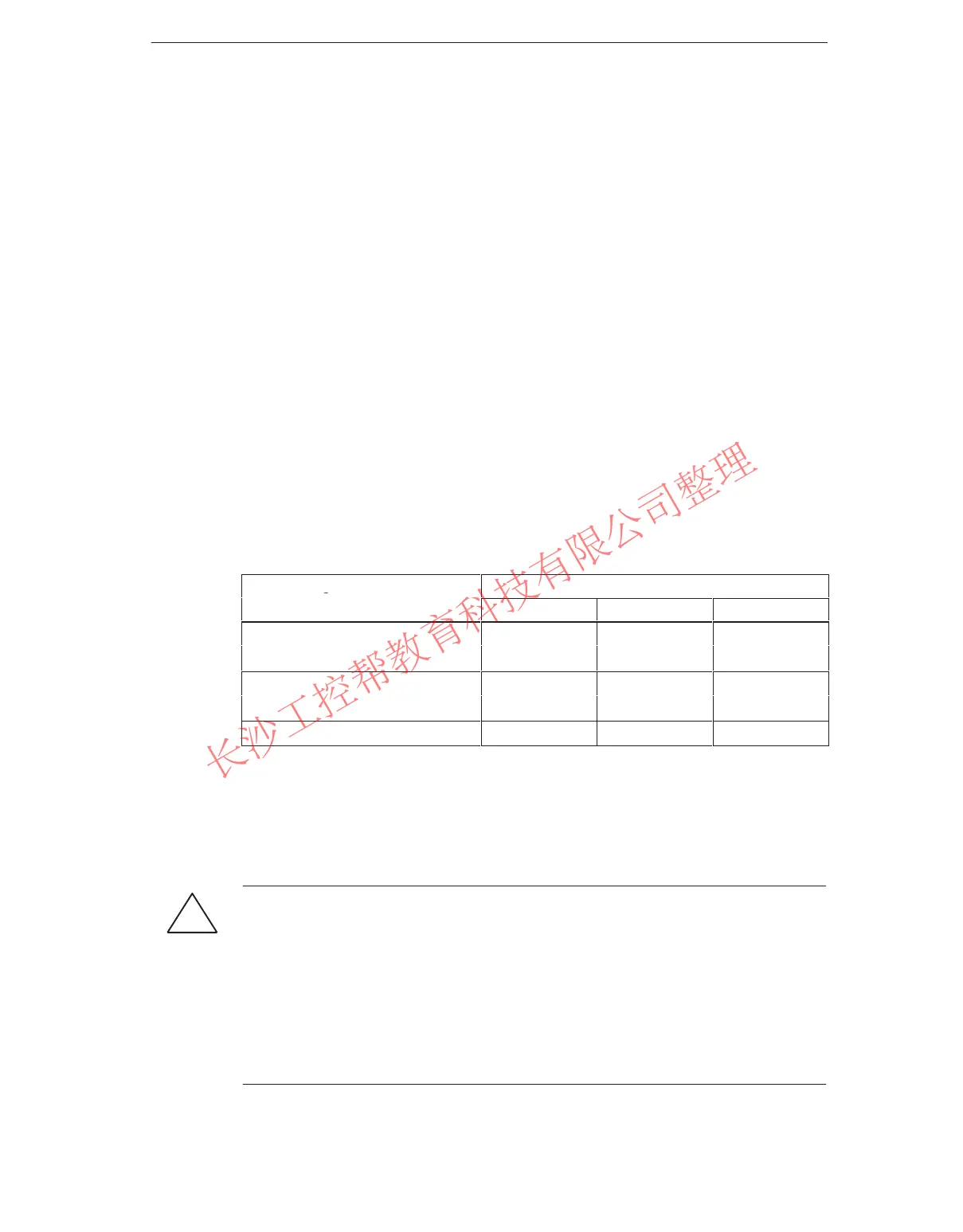
Front Connector Coding on the Signal Modules
Shown in the following table is the allocation between the different front connector
coding keys and individual signal modules.
Signal Modules Color of Front Connector Coding Key
red yellow green
Digital inputs, outputs
> 60 VDC or > 50 VAC
1. Digital inputs, outputs
v 60 VDC or v 50 VAC
Analog inputs, outputs
Plugging In the Front Connector
You can only plug in the connector when the power supply module is installed
(lower mounting screw tightened).
!
Caution
Modules can be damaged.
If, for example, you plug the front connector of a digital input module into a digital
output module, the module can be damaged. If, for example, you plug the front
connector of an analog input module into an analog output module, the module
can be damaged.
When plugging in the front connector, ensure that the module and front connector
are matched.
www.PLCworld.cn

 Loading...


