Installing the S7-400
2-9
S7-400 and M7-400 Programmable Controllers, Installation Manual
C79000-G7076-C424-01
2.4 Mounting and Grounding the Racks
Important Notes on Installation
The S7-400 racks are designed for wall mounting, mounting on rails, and for
installation in frames and cabinets. Their mounting dimensions comply with
DIN 41 494.
According to the UL/CSA and the EU Directive 73/23/EEC (low-voltage directive),
installation in a cabinet, a casing, or a closed operations room is necessary in
order to fulfil the requirements for electrical safety (see
Reference Manual
,
Chapter 1).
In principle, the M7-400 is mounted like an S7-400 except that preassembly is
required (see Section 8.4 “Installing the M7-400”).
Step 1: Retaining Distances Between Devices
You must observe the minimum distances between the rack and neighboring
devices.
You need these minimum clearances during installation and operation
For fitting and removing modules
For fitting and disconnecting the module front connectors
To ensure the air flow required for cooling the modules during operation
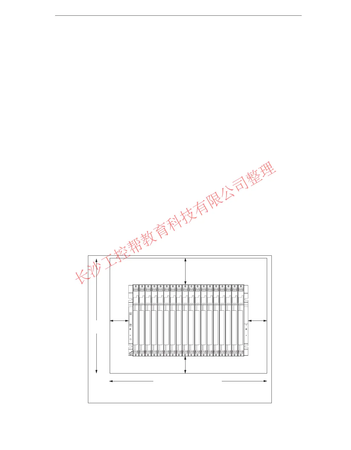
The following figure shows the minimum space you must provide for a rack.
20 mm
20 mm
40 mm
22 mm
522.5 mm (18 slots)
352 mm
Mounting depth, fitted: 237 mm max.
40 mm facilitates the installation of a fan subassembly
*
*
297.5 mm (9 slots)
www.PLCworld.cn

 Loading...


