Installing the S7-400
2-6
S7-400 and M7-400 Programmable Controllers, Installation Manual
C79000-G7076-C424-01
2.2 Assembling the Central Rack (CR) and Expansion Rack (ER)
Function of the racks
The racks of the S7-400 system form the basic framework which accepts the
individual modules. The modules exchange data and signals and are powered via
the backplane bus. The racks are designed for wall mounting, for mounting on
rails, and for installation in frames and cabinets (see Chapter 4).
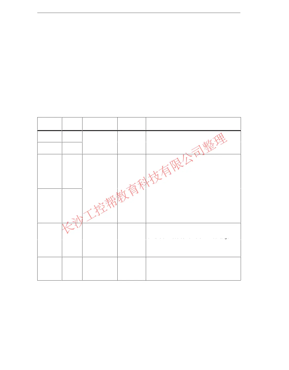
Racks in the S7-400 System
Rack
No. of
Slots
Available
Buses
Application Characteristics
UR1 18
I/O bus
CR
Rack for all module types in the S7-400 and as
central rack for CPUs and their expansion
UR2 9
Communication
bus
or
ER
modules from the M7-400 range (see
Section 8.1).
ER1 18
Restricted I/O
Racks for signal modules (SMs), receive IMs,
and all power supply modules.
The I/O bus has the following restrictions:
Interrupts from modules have no effect
because no interrupt lines exist.
Modules are not supplied with 24 V, i.e.
ER2 9
bus
ERs
,
.
.
modules requiring 24 V cannot be used
(see technical data of the modules).
Modules are neither backed up by the
battery in the power supply module nor by
the voltage applied externally to the CPU or
receive IM (EXT.BATT. socket).
I/O bus,
se
mented
Segmented
Rack for all module types in the S7-400 except
receive IMs and for the CPUs and their
expansion modules from the M7-400 range
CR2 18
Communication
bus, continuous
CR
(see Section 8.1).
The I/O bus is subdivided into 2 I/O bus
segments of 10 and 8 slots respectively.
UR2-H 18
I/O bus,
segmented
Communication
bus, segmented
Fault-tole-
rant
CR or ER
Rack for all module types in the S7-400.
The I/O bus and communication bus are
divided into 2 bus segments, each with 9 slots.
www.PLCworld.cn

 Loading...


