Assembling the M7-400
8-3
S7-400 and M7-400 Programmable Controllers, Installation Manual
C79000-G7076-C424-01
Note
Establish whether there are additional regulations applying to all modules not
described in this manual.
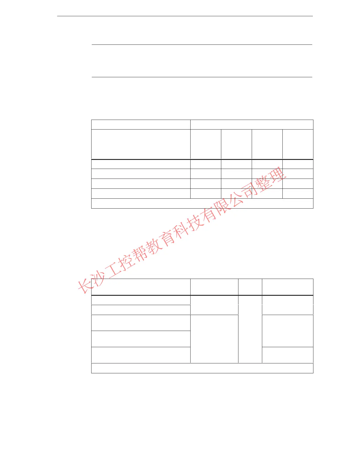
Table 8-2 shows which modules can be used in the different racks.
Table 8-2 Possible Applications of the M7-400 Modules
Racks
Modules
UR1, UR2
as
Central
Rack
UR1, UR2
as
Expansion
Rack
CR2 ER1, ER2
Central Processing Units (CPUs) - -
Expansion Module (EXM)
*
-
*
-
AT Adapter Module (ATM)
*
-
*
-
Mass Storage Module (MSM)
*
-
*
-
* Can only be inserted in conjunction with the CPU.
Dimensions of Modules in the M7-400
There are modules of 25 mm and 50 mm in width in the M7-400 system.
Table 8-3 contains a summary of dimensions of the modules used in the M7-400.
Table 8-3 Dimensions of Modules in the M7-400 System
Module
Slots Occupied Height Depth (Depth
when Fitted)
CPU 486-3 (incl. mode switch)
219 mm
CPU 488-3 (incl. mode switch)
2
(236.5 mm)
Expansion Module
EXM 478
210 mm
Mass Storage Module
MSM 478
1
mm
(227.5 mm)
AT Adapter Module
ATM 478
230 mm*
(247.5 mm*)
* The mounting depth is governed by the installed AT card and its connector.
www.PLCworld.cn

 Loading...


