Networking
5-21
S7-400 and M7-400 Programmable Controllers, Installation Manual
C79000-G7076-C424-01
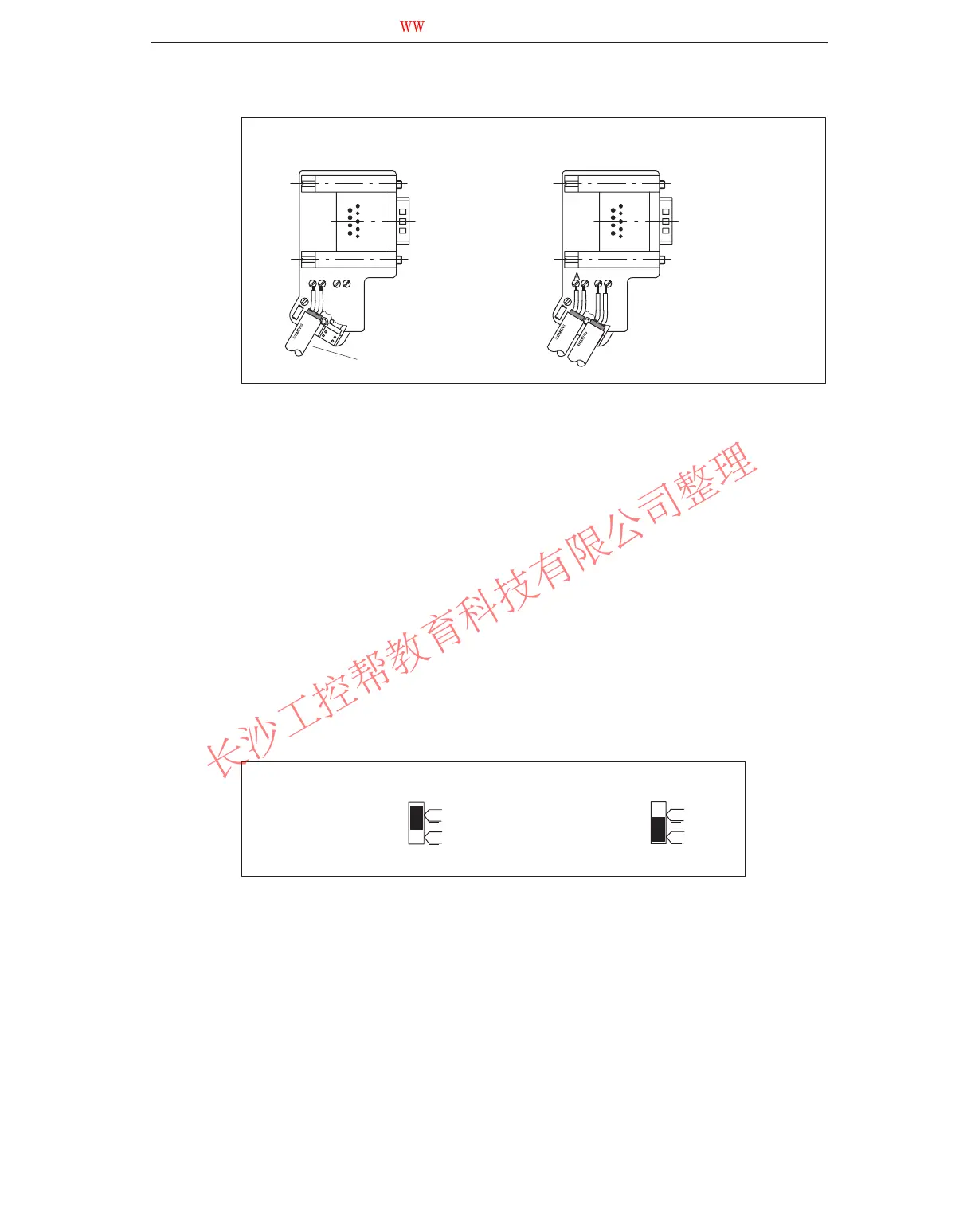
Bus cable connection for first
and last station on the bus
Bus cable connection for all
other stations on the bus
A B A B
A B A B
The bus cable can be
connected either right or
left.
6. Retighten the clamp hinge cover.
Ensure that the bare cable shield is under the shield clamp.
7. Tighten the screw terminals for the green and red cores.
8. Close the cover of the bus connector.
9. Screw the housing on.
Connecting the Bus Connector
To connect the bus connector, proceed as follows:
1. Plug the bus connector into the module.
2. Screw the bus connector into the module.
3. If the bus connector, order no. 6ES7 972-0B.20-0XA0, is situated at the
beginning or end of a segment, you must switch on the terminating resistor.
Terminating
resistor
switched on
Terminating resistor
not switched on
on
off
on
off
Ensure that power is always applied to the stations at which the terminating
resistor is situated, during startup and operation.
www.PLCworld.cn

 Loading...


