Assembling the M7-400
8-6
S7-400 and M7-400 Programmable Controllers, Installation Manual
C79000-G7076-C424-01
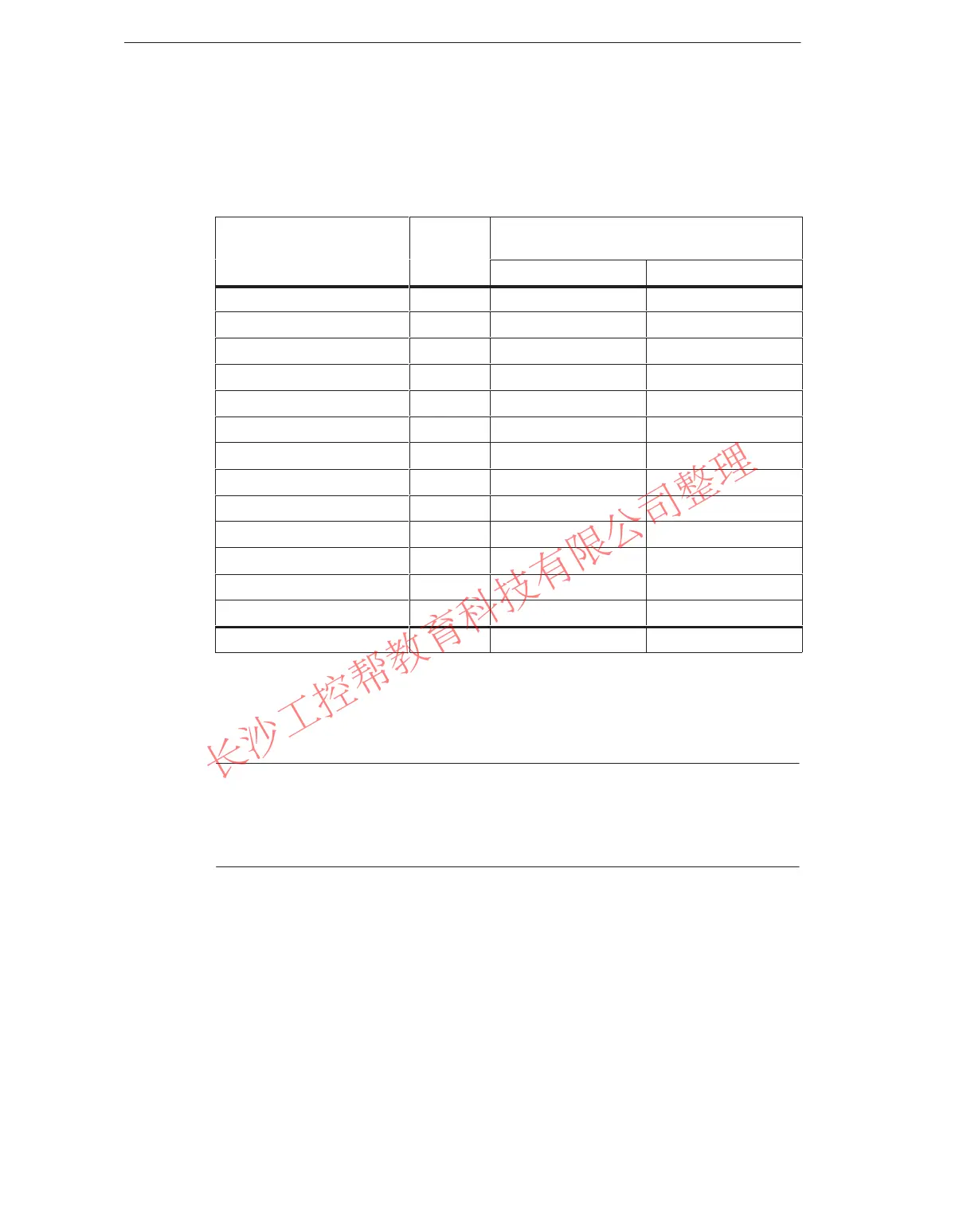
With the details from the individual data sheets, you can calculate Current
Consumption I in this rack as follows:
Table 8-4 Calculation Example for Power Supply Module
Module
Slots
Occupied
+5 VDC
(Max. Current Consumption Values)
I / Module I Total
CPU 488-3 2 4500 mA 4500 mA
IF 962-VGA 600 mA 600 mA
IF 962-COM 100 mA 100 mA
EXM 478 1 200 mA 200 mA
IF 961-DIO 85 mA 170 mA
IF 961-AIO 85 mA 85 mA
MSM 478 1 1000 mA 1000 mA
ATM 478 1 120 mA 120 mA
Short AT Module (LAN) 1400 mA 1400 mA
SM 431; AI 16 x 16 bits 3 700 mA 2.100 mA
SM 421; DI 32 x 34 VDC 3 30 mA 90 mA
SM 422; DO 32 x 34 VDC 3 200 mA 600 mA
IM 460-0 1 110 mA 110 mA
Total 15 10075 mA
From the data in Table 8-4, you see that to cover the current consumption
calculated here, you must install a power supply module PS 407 20A (for a
120/230 VAC supply) or PS 405 20A (for a 24 VDC supply) in the rack.
Note
If you wish to connect an expansion rack to the central rack via a send IM with
current transfer, you must take into account the current consumption of this
expansion rack when choosing the power supply module.
www.PLCworld.cn

 Loading...


