Assembling the M7-400
8-22
S7-400 and M7-400 Programmable Controllers, Installation Manual
C79000-G7076-C424-01
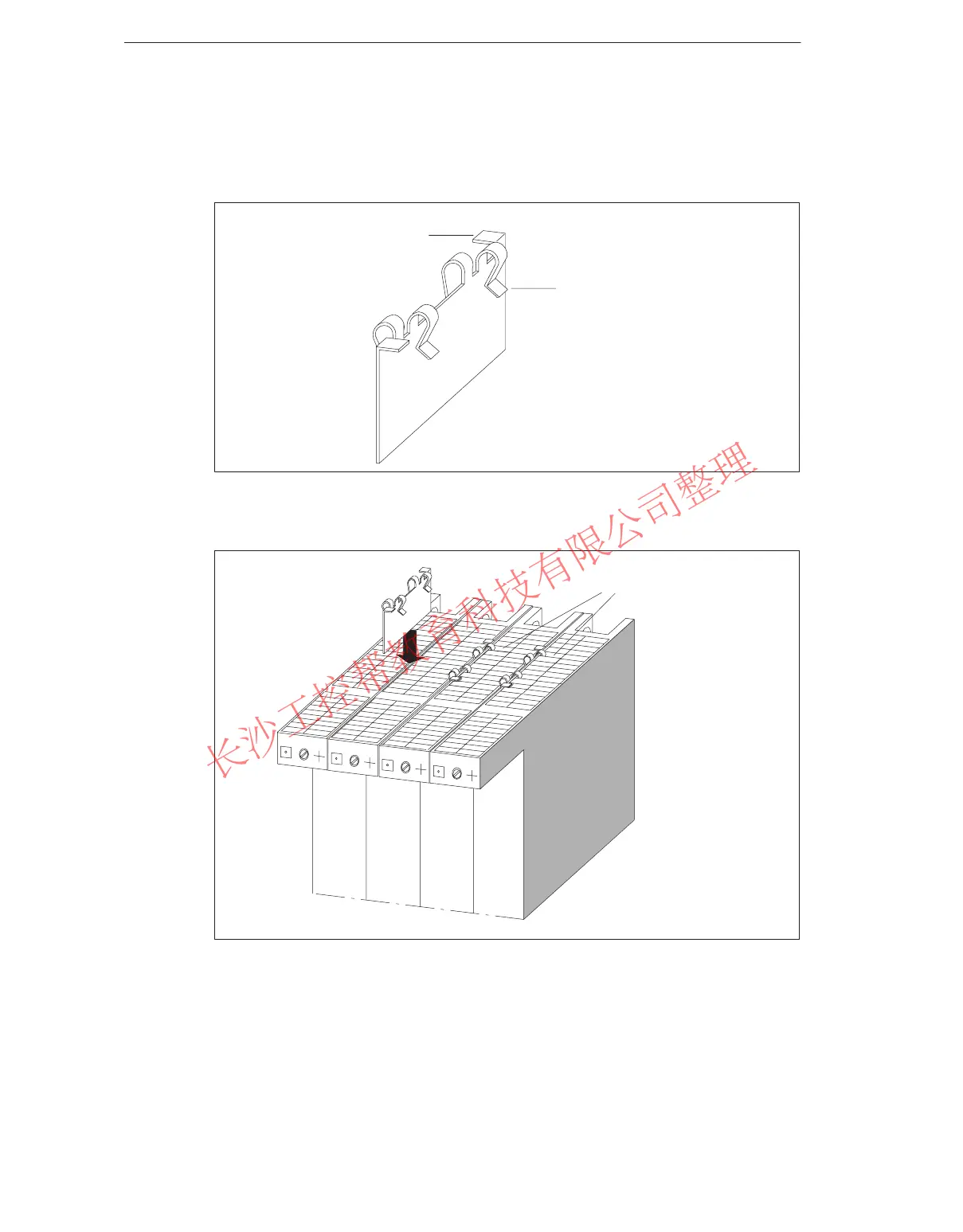
3. Press the connecting clip on its two 90° ends downward until it engages. Figure
8-11 shows a connecting clip in its final position.
4. Carry out steps 1 to 3 similarly on the bottom of the modules to be secured.
Bent clip end
Clip end bent
90°
Figure 8-10 Connecting Clip
Fifth grid hole
Figure 8-11 Securing the Modules with Connecting Clips (Schematic Diagram)
www.PLCworld.cn

 Loading...


