Assembling the M7-400
8-38
S7-400 and M7-400 Programmable Controllers, Installation Manual
C79000-G7076-C424-01
Connecting without Control Cables
If the data traffic via the COM interface is to be controlled exclusively via the data
lines, a connecting cable as described below is sufficient for connecting your CPU
to a programming device.
If the free COM interface of your programming device has a 9-pin subminiature D
male connector, you can use Table 8-9 below for the pin assignments of the
connecting cable.
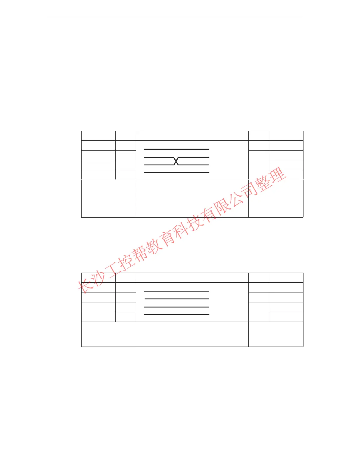
Table 8-9 Pin Assignments of the Cable for Connecting a CPU via IF to the COM Interface
of a Programming Device with 9-pin Sub. D Male Connector
Signal Pin Connection Pin Signal
E1 / GND U U E1 / GND
D2 / RxD 2 2 D2 / RxD
D1 / TxD 3 3 D1 / TxD
E2 / GND 5 5 E2 / GND
9-pin sub.
D female conn.
(COM1 for IF)
Pin U = housing (shield)
Length: 10 m max.
9-pin sub.
D female conn.
(COMx for
programming
device)
If the free COM interface of your programming device has a 25-pin subminiature D
female connector, you can use Table 8-10 below for the pin assignments of the
connecting cable.
Table 8-10 Pin Assignments of the Cable for Connecting a CPU via IF to the COM Interface
of a Programming Device with 25-pin Sub. D Female Connector
Signal
Pin Connection Pin Signal
E1 / GND U U E1 / GND
D2 / RxD 2
2 D1 / TxD
D1 / TxD 3 3 D2 / RxD
E2 / GND 5 7 E2 / GND
9-pin sub.
D female conn.
(COM1 for IF)
Pin U = housing (shield)
Length: 10 m max.
25-pin sub.
D male conn.
(COMx for PG)
www.PLCworld.cn

 Loading...


