Installing the S7-400
2-3
S7-400 and M7-400 Programmable Controllers, Installation Manual
C79000-G7076-C424-01
Connecting the CR and ER(s)
To connect one or more ERs to a CR, you must fit one or more send IMs in the
CR.
The send IMs have two interfaces. You can connect one chain of up to four ERs to
each of the two interfaces of a send IM in the CR.
Different IMs are available for local connection and remote connection.
Connecting with a 5 V Supply
For a local connection with the IM 460-1 and IM 461-1, the 5 V supply voltage is
also transferred via the interface modules. There must therefore be no power
supply module inserted in an ER connected to an IM 460-1/IM 461-1.
Up to 5 A may flow through each of the two interfaces of an IM 460-1. This means
that each ER connected via an IM 460-1/461-1 can be powered with a maximum of
5 A at 5 V. For further details, see the
Reference Manual,
Chapter 7.
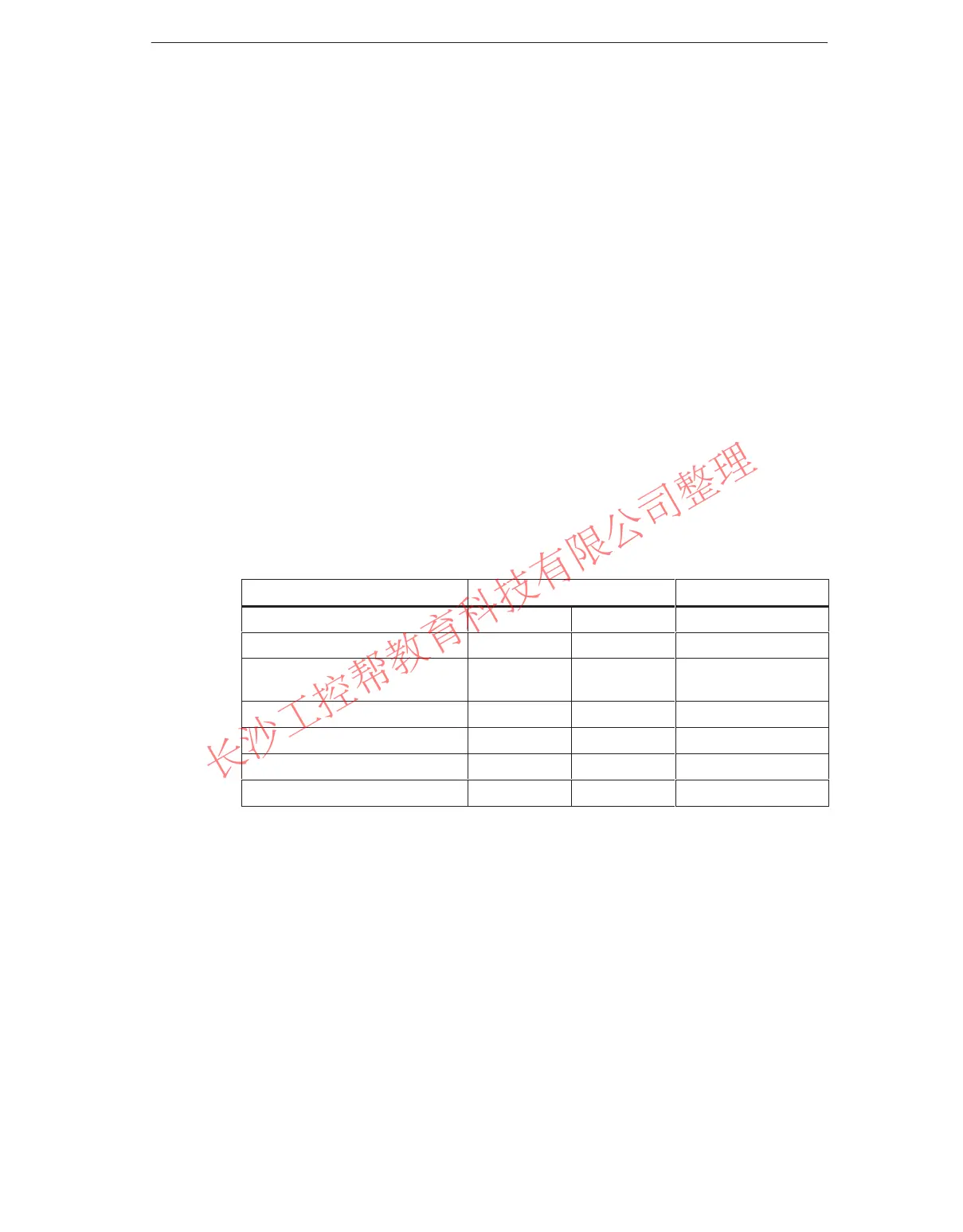
Overview of the Connections
Observe the connection rules at the end of this section.
Local Connection Remote Connection
Send IM 460-0 460-1 460-3
Receive IM 461-0 461-1 461-3
Max. no. of connectable ERs per
chain
4 1 4
Max. distance 3 m 1.5 m 102.25 m
5 V transfer no yes no
Max. current flow per interface - 5 A -
Communication bus transmission yes no yes
www.PLCworld.cn

 Loading...


