Wiring the S7-400
4-9
S7-400 and M7-400 Programmable Controllers, Installation Manual
C79000-G7076-C424-01
S7-400 in the Overall Installation
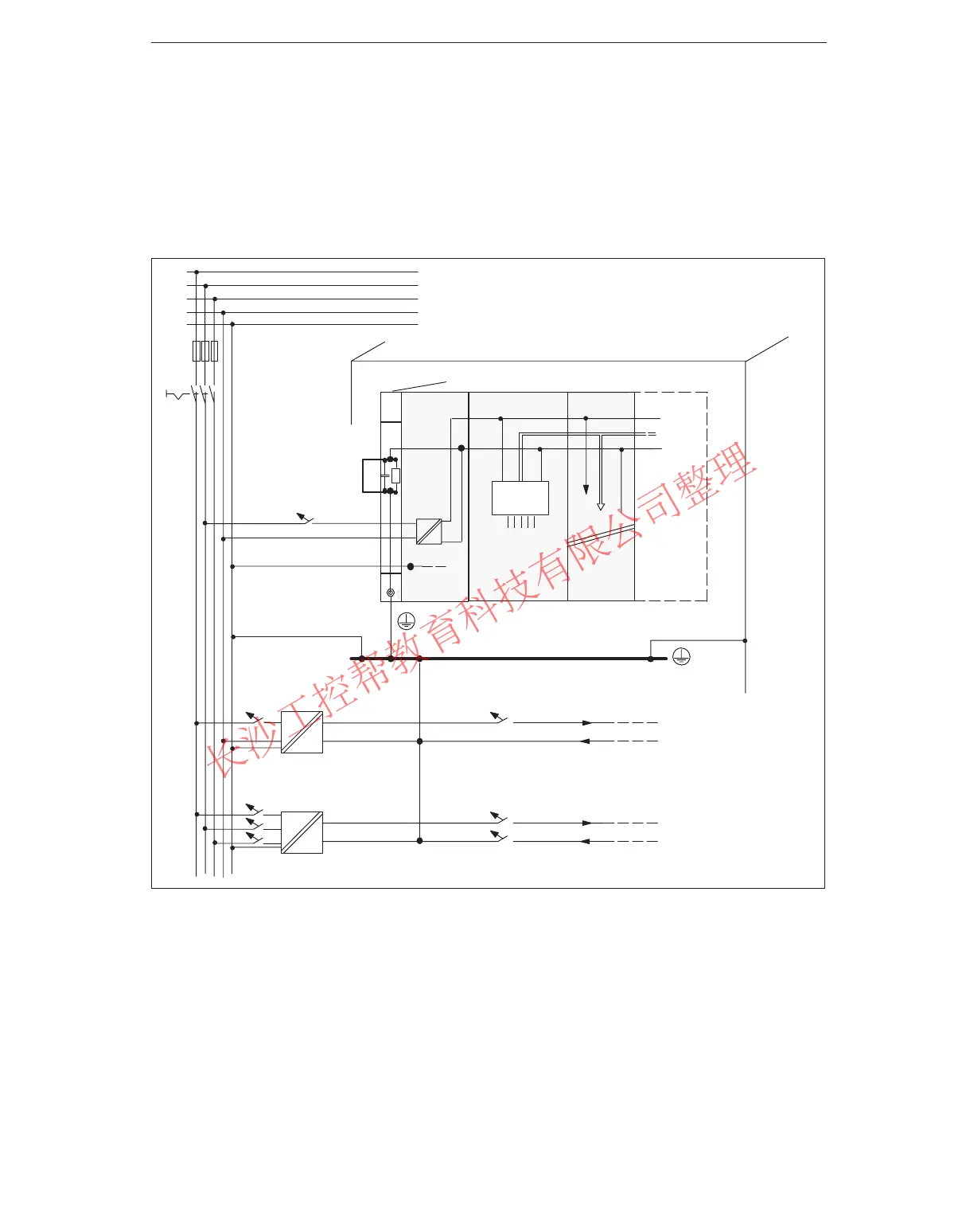
Shown in Figure 4-1 is the position of the S7-400 in the overall installation (load
current power supply and grounding concept) with supply from a TN-S system.
Note: The arrangement of supply terminals shown is not the actual arrangement; it
has been chosen for reasons of clarity.
Ground bus in cabinet
N
L1
L +
M
PS CPU
L1
L2
L3
N
Load circuit
24 to 230 VAC for AC modules
Load circuit 5 to 60 VDC for isolated
DC modules
Cabinet
AC
AC
AC
DC
Signal modules
Low-voltage distribution e.g. TN-S system (3 x 400 V)
PE
SM
Racks
PE
Data
Figure 4-1 Operating the S7-400 from a Grounded Supply
www.PLCworld.cn

 Loading...


