Connecting cables
11
11.1 X27 (RS 422/485) Interface of the CP 440
Pin Assignment
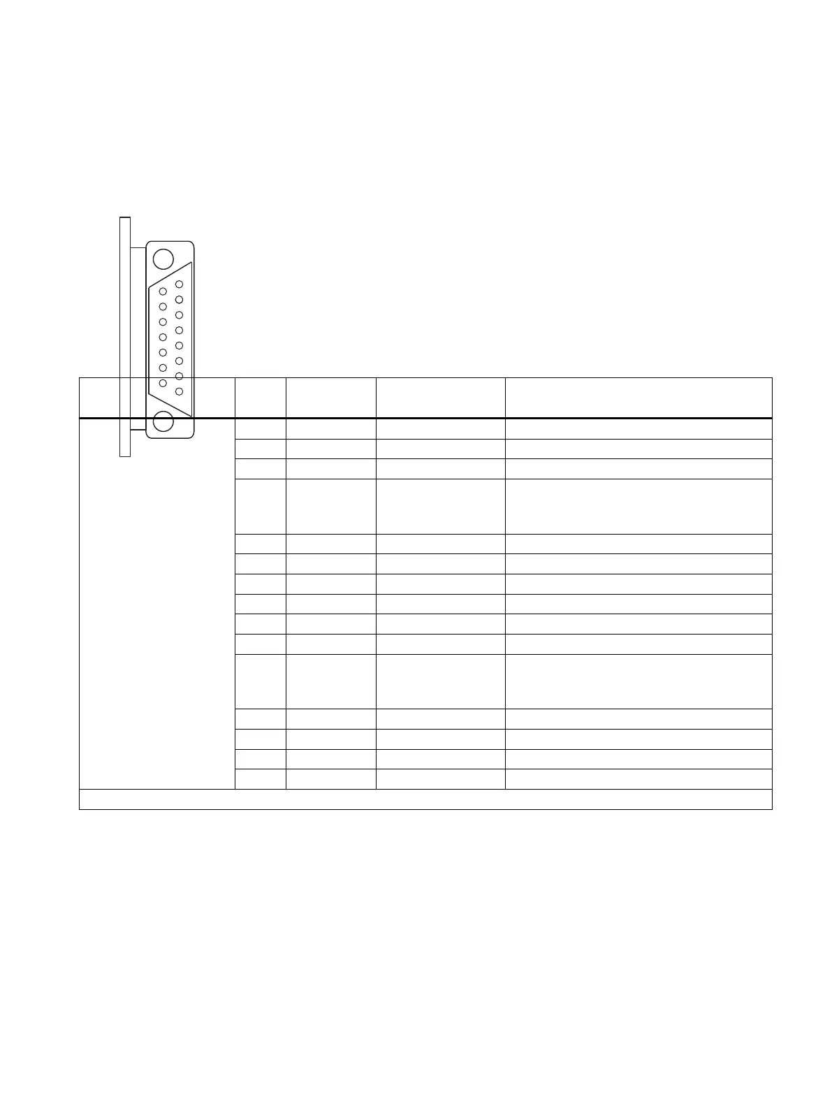
The table below shows the pin assignment for the 15-pin subminiature D female connector in
the front panel of the CP 440.
Table 11-1 Pin Assignment for the 15-Pin Subminiature D Female Connector of the Integrated Interface of the CP 440
Female connector on
CP 440-RS 422/485
*
Pin Designation Input/Output Meaning
1 - - -
2 T (A)- Output Transmitted data (four-wire operation)
3 - - -
4 R (A)/T (A)- Input
Input/Output
Received data (four-wire operation)
Received/transmitted data (two-wire opera‐
tion)
5 - - -
6 - - -
7 - - -
8 GND - Functional ground (isolated)
9 T (B)+ Output Transmitted data (four-wire operation)
10 - - -
11 R (B)/T (B)+ Input
Input/Output
Received data (four-wire operation)
Received/transmitted data (two-wire opera‐
tion)
12 - - -
13 - - -
14 - - -
15 - - -
* View from the front
11.2 Cables
Connecting cables
If you make your own connecting cables you must remember that unconnected inputs at the
communication partner may have to be connected to open-circuit potential.
Point-to-point connection CP 440 Installation and Parameter Assignment
Equipment Manual, 03/2022, A5E00057742-AE 127

 Loading...


