EasyManuals Logo

Siemens Simatic S7-400 Equipment Manual

Siemens Simatic S7-400
140 pages
To Next Page IconTo Next Page
To Previous Page IconTo Previous Page
Page #63 background imageLoading...
Page #63 background image
Initial state of receive line
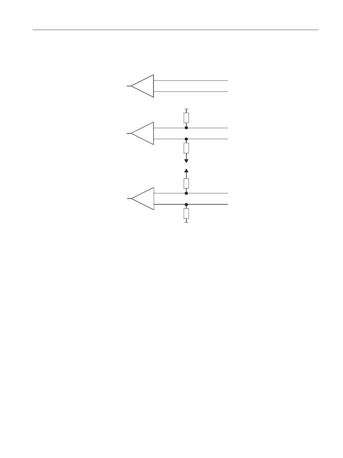
The following 󹪝gure illustrates the wiring of the receiver at the X27 (RS 422/485) interface:
0 V
0 V
5 V
5 V
R(B) +
R(A)
R(B) +
R(A)
R(B) +
R(A)
R(A) 5 V / R(B) 0 V
R(A) 0 V / R(B) 5 V
none
Figure 5-1 Wiring of the Recipient at the X27 (RS 422/485) Interface (ASCII Driver)
See also
Data Transmission with the ASCII Driver (Page 23)
5.4.4 Con󹪝guration Data of the 3964(R) Procedure
Introduction
Using the parameter assignment data of the 3964(R) procedure, you can adjust the CP 440 to
suit the properties of its communication partner.
Con󹪝guring and Parameter Assignment the CP 440
5.4 Con󹪝guration data
Point-to-point connection CP 440 Installation and Parameter Assignment
Equipment Manual, 03/2022, A5E00057742-AE 63

Table of Contents

Other manuals for Siemens Simatic S7-400

Questions and Answers:

Question and Answer IconNeed help?

Do you have a question about the Siemens Simatic S7-400 and is the answer not in the manual?

Siemens Simatic S7-400 Specifications

General IconGeneral
Programming LanguageSTEP 7 (LAD, FBD, STL, SCL, GRAPH)
Communication InterfacesMPI, PROFIBUS
Power Supply24 V DC, 120/230 V AC (Power supply modules are separate and chosen based on system requirements)
Operating Temperature0°C to 60°C
MountingRack mounting
ProcessorCPU 412-1, CPU 414-2, CPU 416-2, CPU 417-4 (Different CPUs offer varying performance and features)
Relative Humidity5 to 95% (non-condensing)

Related product manuals