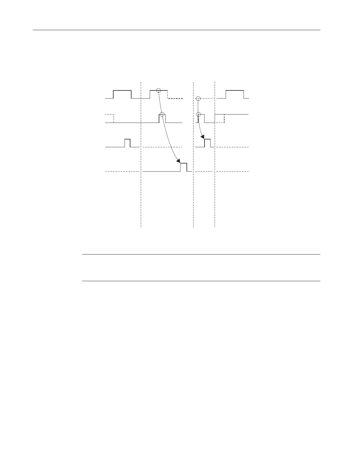
Time Sequence Chart for the SEND_440 FB
The gure below illustrates the behavior of the DONE and ERROR parameters, depending on how
the REQ and R inputs are wired.
5(4
5
'21(
(5525
6HQGLQJUHTXHVW
7HUPLQDWLRQZLWKRXWHUURU
7UDQVIHU5(6(7
7UDQVIHU5(6(7
7HUPLQDWLRQZLWKRXWHUURU
5HTXHVWLV
QRWH[HFXWHG
6HQGLQJLV
WXUQHGRII
7HUPLQDWLRQZLWKHUURU
VWQWK6(1'SDUW
Figure 6-1 Time Sequence Chart for the 10 SEND_440 FB
Note
The REQ input is edge-triggered. A positive edge at the REQ input is adequate. It is not required
that the RLO (result of logical operation) is "1" during the whole transmission procedure.
6.3.2 S7 Receives Data from a Communication Partner, 9 RECV_440 FB
How FB SEND_440 Works
The RECV_440 FB transmits data from the CP 440 to an S7 data area specied by the DB_NO,
DBB_NO and LEN parameters. The RECV_440 FB is called cyclically for data transmission or,
alternatively, statically in a time-controlled program (without conditions).
With the (static) signal state "1" at parameter EN_R, the software checks whether data can be
read by the CP 440. An active transmission can be aborted with signal state "0" at the EN_R
parameter. The aborted receive request is terminated with an error message (STATUS output).
Receiving is deactivated as long as the EN_R parameter has the signal state "0". A data
transmission operation can run over several calls (program cycles), depending on the amount of
data involved.
Communication via Function Blocks
6.3 Using the Function Blocks
Point-to-point connection CP 440 Installation and Parameter Assignment
Equipment Manual, 03/2022, A5E00057742-AE 79

 Loading...


