Time Sequence Chart for the RES_RECV FB
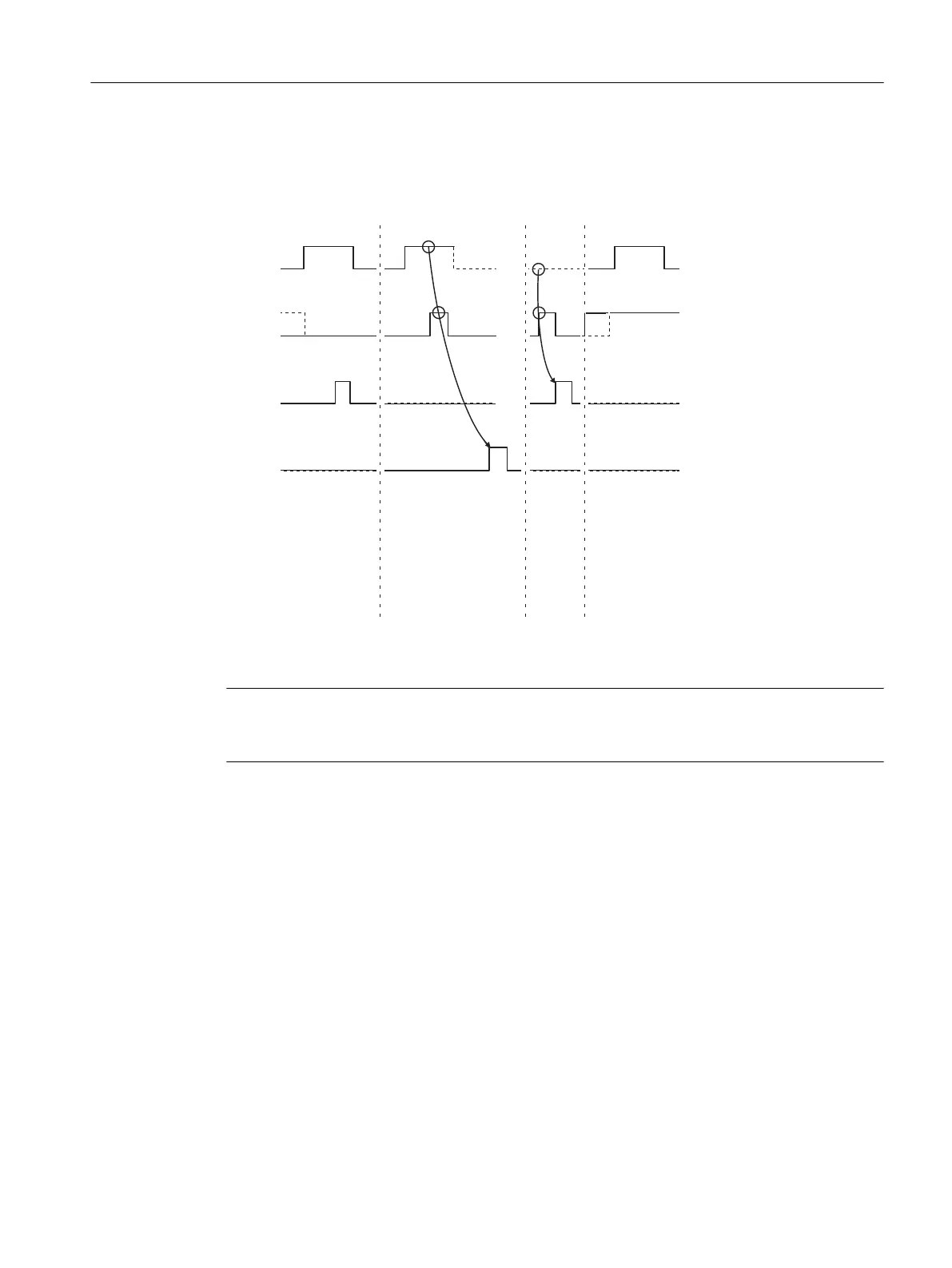
The gure below illustrates the behavior of the DONE and ERROR parameters, depending on how
the REQ and R inputs are wired.
REQ
R
DONE
ERROR
Deleting the receive
buffer
Completion without error
RESET transmitted
Completion with error
RESET transmitted
Completion without error
Job not
executed
Figure 6-3 Time Sequence Chart for the 11 RES_RECV FB
Note
The REQ input is edge-triggered. A positive edge at the REQ input is adequate. It is not required
that the RLO (result of logical operation) is "1" during the whole transmission procedure.
6.4 Programming the Function Blocks
6.4.1 Supplying the block parameters
Direct/Indirect Parameter Assignment
With STEP 7 the data blocks cannot be indirectly assigned parameters (parameters transferred
in the currently selected data block) as they can with STEP 5.
All block parameters accept both constants and variables, so the distinction between direct and
indirect parameter assignment is no longer necessary in STEP 7.
Communication via Function Blocks
6.4 Programming the Function Blocks
Point-to-point connection CP 440 Installation and Parameter Assignment
Equipment Manual, 03/2022, A5E00057742-AE 85

 Loading...


