Signal modules
5.1 SM500 signal module
SIMATIC TDC hardware
System Manual, 08/2017, A5E01114865-AL
113
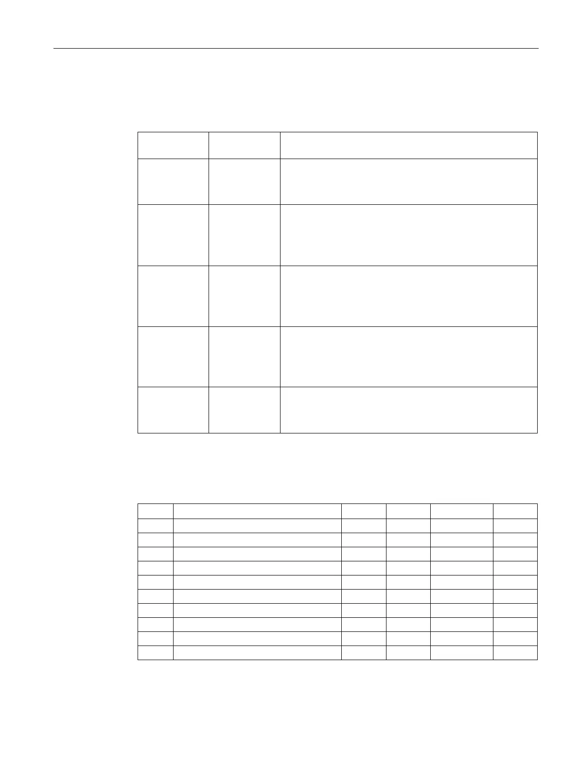
Terminal assignment, interface modules
Table 5- 8 Terminal assignment of the interface modules
SB10
x
5x
1:1 screw terminal connection
• Signal
• Reference potential (ground or P24)
SB60
x1
x2
x4
Digital inputs 115/120 V
• Ground
• Digital input 115 V
• Digital input 120 V
SB61
x
1x
5x
Digital inputs 24/48 V
• Digital input 24 V
• Digital input 48 V
• Reference
SB70
x1
x2
x4
Digital outputs (relay)
• Root (center contact)
• NC contact
• NO contact
SB71
x
5x
Digital outputs (transistor)
• Signal
• Ground
Terminal assignment at cable SC62, end A
Table 5- 9 Terminal assignments of the interface modules at connector X3, SC62 cable end A
1 Digital output 1 1 1/51 11/12/14 1/51