More user manuals on ManualsBase.com
Configur.
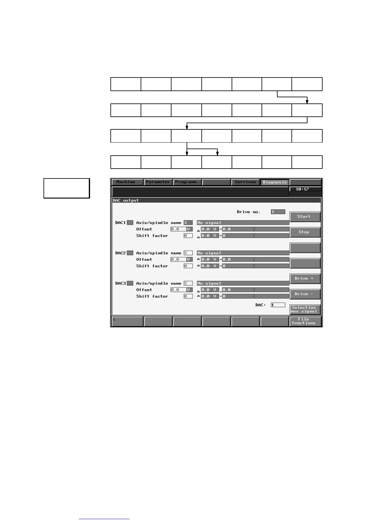
DAC
09.95
Siemens AG 2001 All Rights Reserved 6FC5197–jAA50
9–34
SINUMERIK 840C (IA)
Note The test sockets on 611D modules have an output voltage of between 0 and 5 V;
611A modules have a +/–10 V output. The test sockets can be evaluated in the
usual way. These sockets are not intended for use in normal operation.
Anwahl
Diagnosis
Drive servo
startup
Start-up
Configur.
DAC
Configur.
mixed I/O
Fig. 9.14
Explanation In this display, the output DACs are assigned via drive selection (+/–) and speci-
fication of the axis/spindle name.
The offset input values must make allowance for the output range of the analog
voltage signal. The 611D drive module DACs have an output range of –2.5 V to
2.5 V.
Since the DAC resolution is limited (8 bits), a window can be placed over the
output value by means of the shift factor, i.e. the signal output is decreased
(normalization) when a negative shift factor is input and is increased
(normalization) with a positive shift factor. The input limits for the shift factor vary
for SERVO, FDD and MSD:
9 Drive Servo Start-Up Application (as from SW 3)
9.4 Mixed I/O configuration and digital-analog converter, DAC (as from SW 3)
 Loading...


