Mechanical mounting
6.3 Installing/removing the rotor
SIMOTICS M-1FE2 built-in motors
Hardware Installation Manual, 04/2020, A5E50074509B AA
103
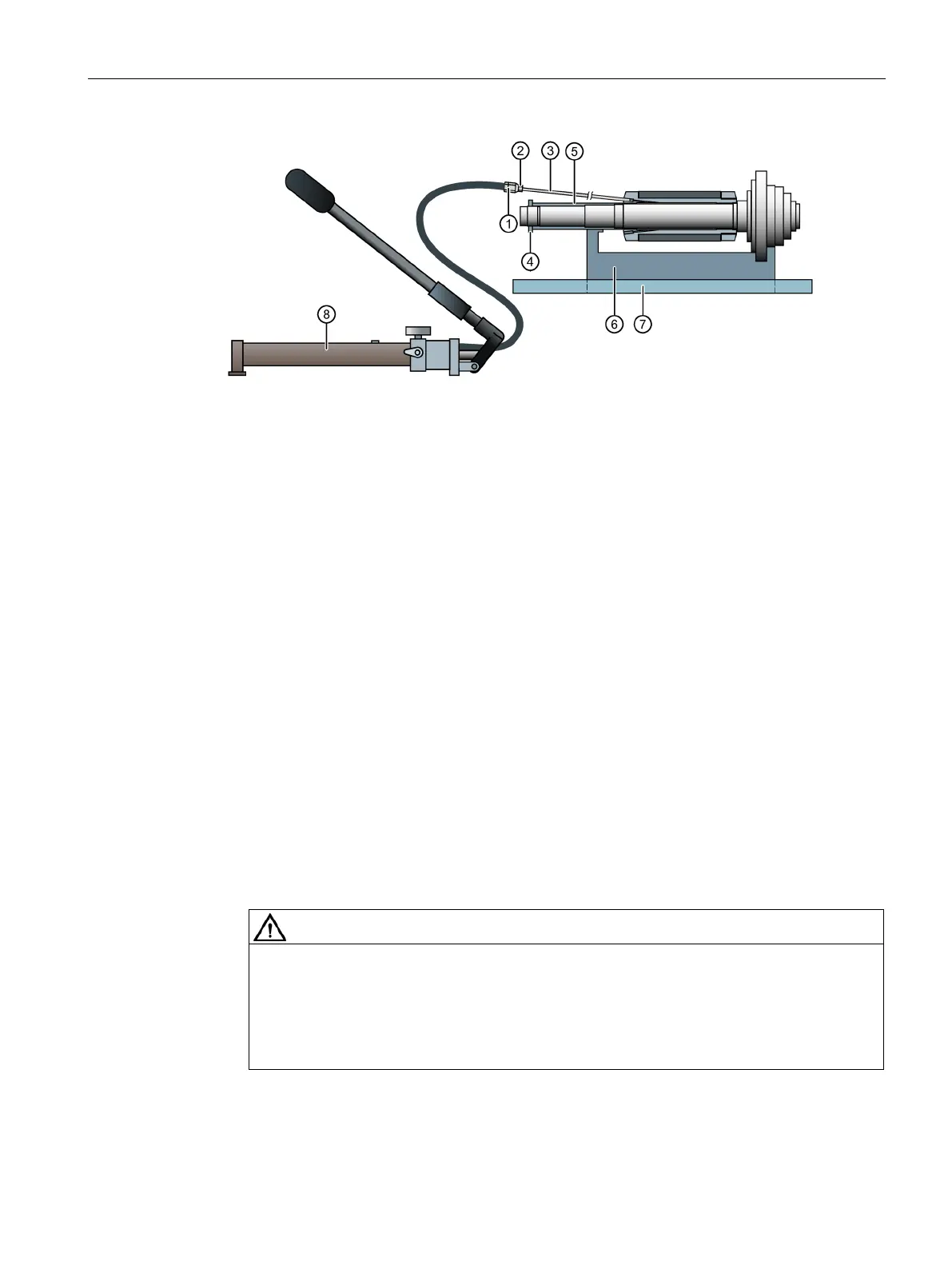
Connection hydraulic hand pump
Supporting fixture (prism)
1)
1)
1)
For synchronous version made of non-magnetic material
Figure 6-8 Design of the equipment for stress compensation and realignment (example)
1. Unscrew both grub screws from the rotor core sleeve.
2. Wrap the threaded shoulder on the extension tube and the second grub screw with Teflon
sealing tape.
3. Screw the extension tube firmly into the sleeve of the rotor core.
4. Place the rotor core with spindle shaft, slotted nut and the spacing sleeve on the prism.
5. Attach the oil hand pump.
6. Vent the hydraulic system.
7. Screw the second grub screw with Teflon sealing tape tightly into the sleeve thread.
8. Force the oil with the hand pump slowly until the pressure of approx. 50 MPa (500 bar) is
reached.
Danger to life caused by oil under high pressure
The spurting of oil and/or mechanical damage from the hydraulic system can cause
severe injury or death.
• Use only intact devices and tools.
• Observe the prescribed pressures.
9. Allow the oil to act for approximately 15 minutes.
→ The oil penetrates the fitting gaps and distributes itself.

 Loading...


