Connection
7.2 Electrical connection
SIMOTICS M-1FE2 built-in motors
Hardware Installation Manual, 04/2020, A5E50074509B AA
159
7.2.11 Connection assignment of the encoder
encoders are not included in the scope of delivery.
More detailed information is provided in the SINAMICS documentation.
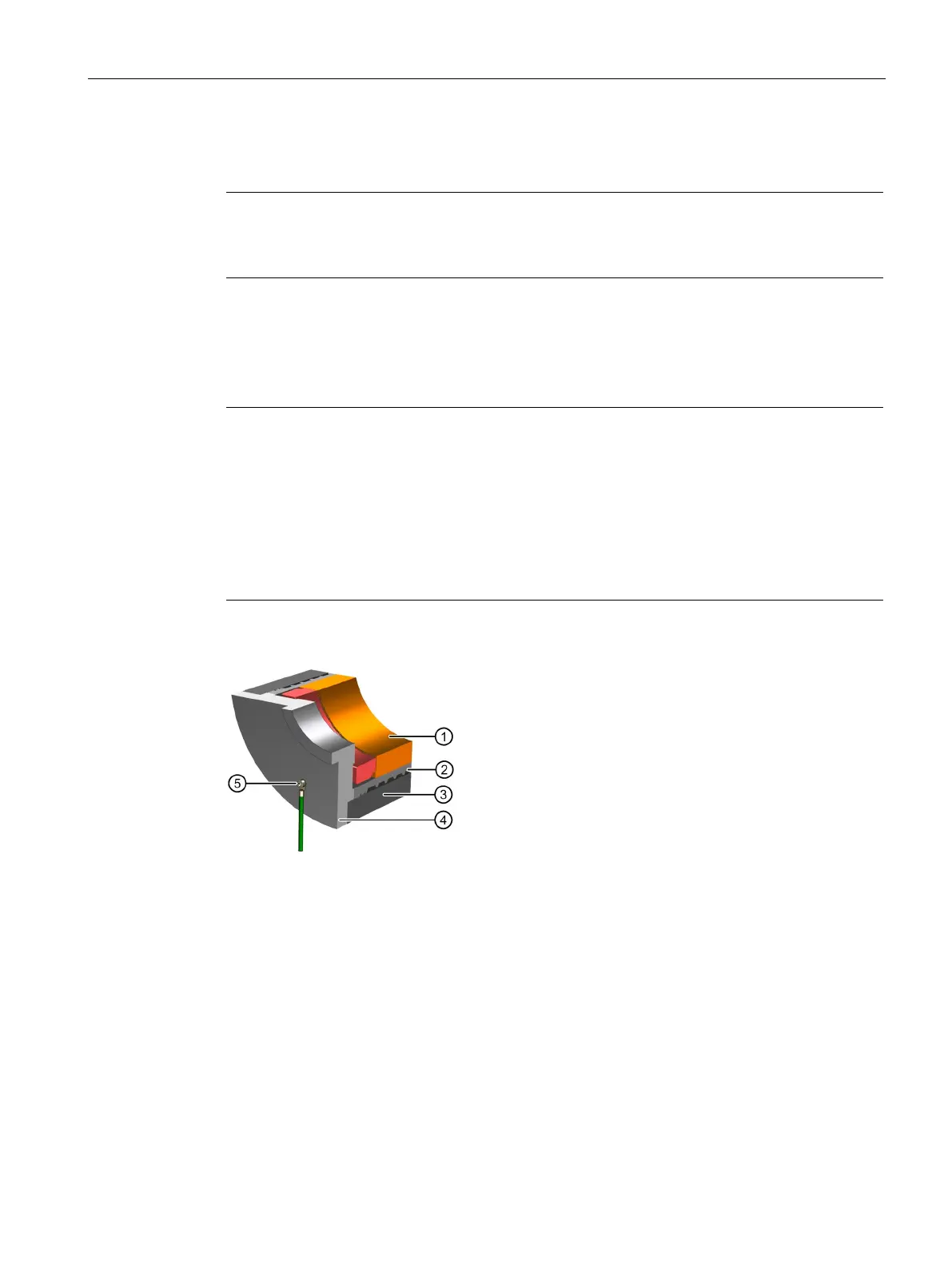
7.2.12 Recommended grounding
Note
A protective conductor / bearing shield must be connected at the spindle box through a good
electric
al connection.
The spindle housing / bearing shield must be electrically connected to the cooling jacket.
Use a protective conductor with the required minimum cross-section.
Ground so there is a good conductive transition between the protective conductor and
spindle box protected against corrosion (e.g. bare contact surfaces with a coating of
Vaseline).
Ground connection with M8 screw
Figure 7-13 Recommended grounding

 Loading...


