Mechanical mounting
6.3 Installing/removing the rotor
SIMOTICS M-1FE2 built-in motors
106 Hardware Installation Manual, 04/2020, A5E50074509B AA
Depending on the motor type, the provided accompanying balancing weights normally permit
the additional compensation:
Additional minimum possible compensation of
imbalance during fine balancing
1)
(gmm)
Number of balancing weights
(units) provided
2200
16
1FE2185-8
3200
22
1
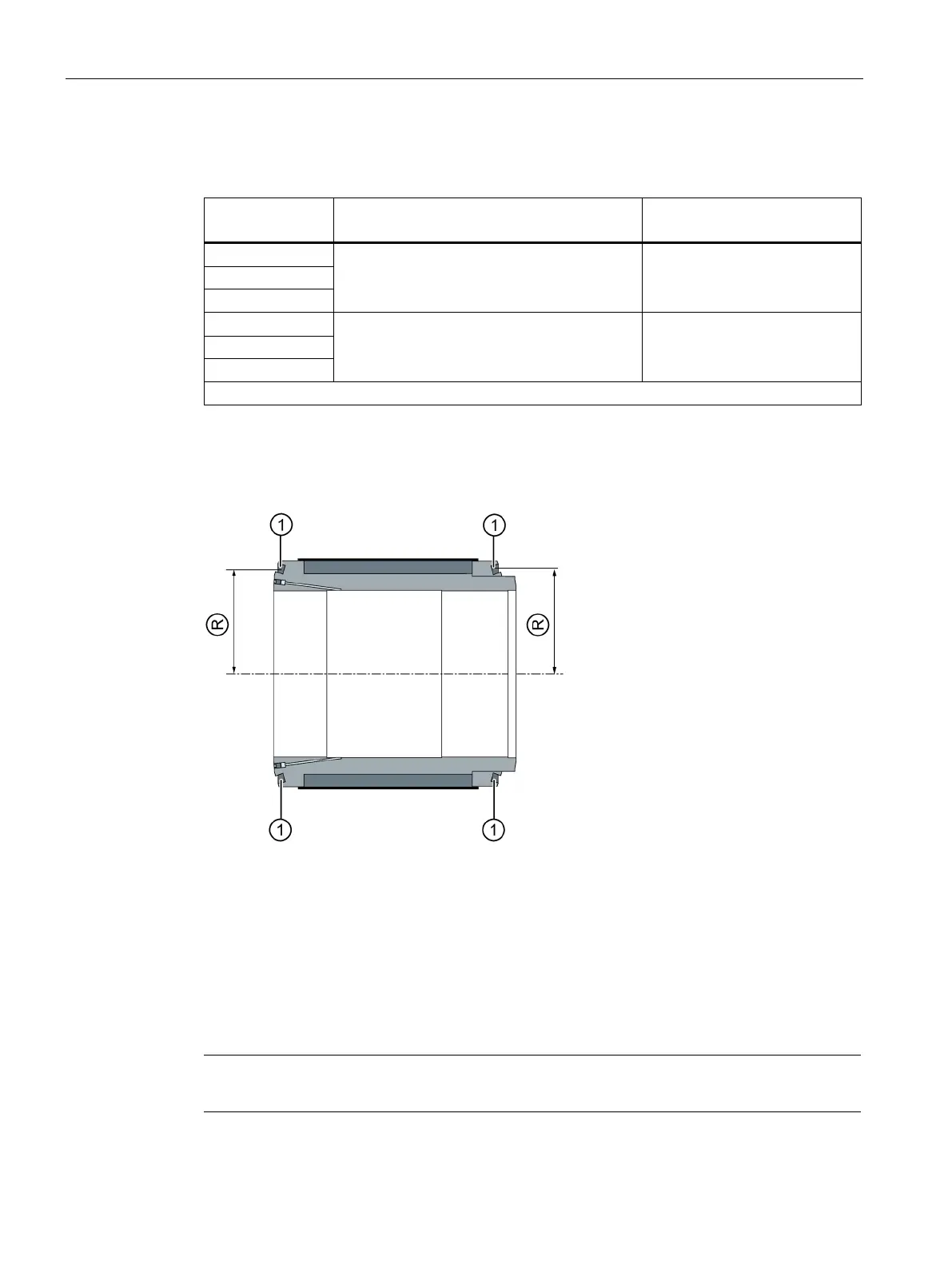
Design of the rotor core
For balancing, the rotor has circumferential grooves ① (balancing planes) in which you
insert and position the balancing weights.
Encircling groove for accepting the balancing weights
Balancing radius = 128.2 mm
Figure 6-10 Structural preparation of the rotor core for balancing
Preconditions for balancing
The rotor core is mounted on the spindle shaft.
The rotor is located in the balancing device.
Note
The spindle manufacturer
is responsible for verifying the balancing system.

 Loading...


