Mechanical mounting
6.3 Installing/removing the rotor
SIMOTICS M-1FE2 built-in motors
112 Hardware Installation Manual, 04/2020, A5E50074509B AA
Procedure for removal using the oil pressing procedure
Environmental harm due to leaking oil
The forcing of oil can cause oil to escape and result in environmental damage.
• Catch any escaping oil.
• Bind the escaping oil with a suitable oil binding agent.
• Dispose of the oil and oil binding agent in accordance with the legal regulations.
Note
Different shape
The spindle shaft is supplied by the spindle manufacturer. The shape of the spindle shaft
may differ from the illustration
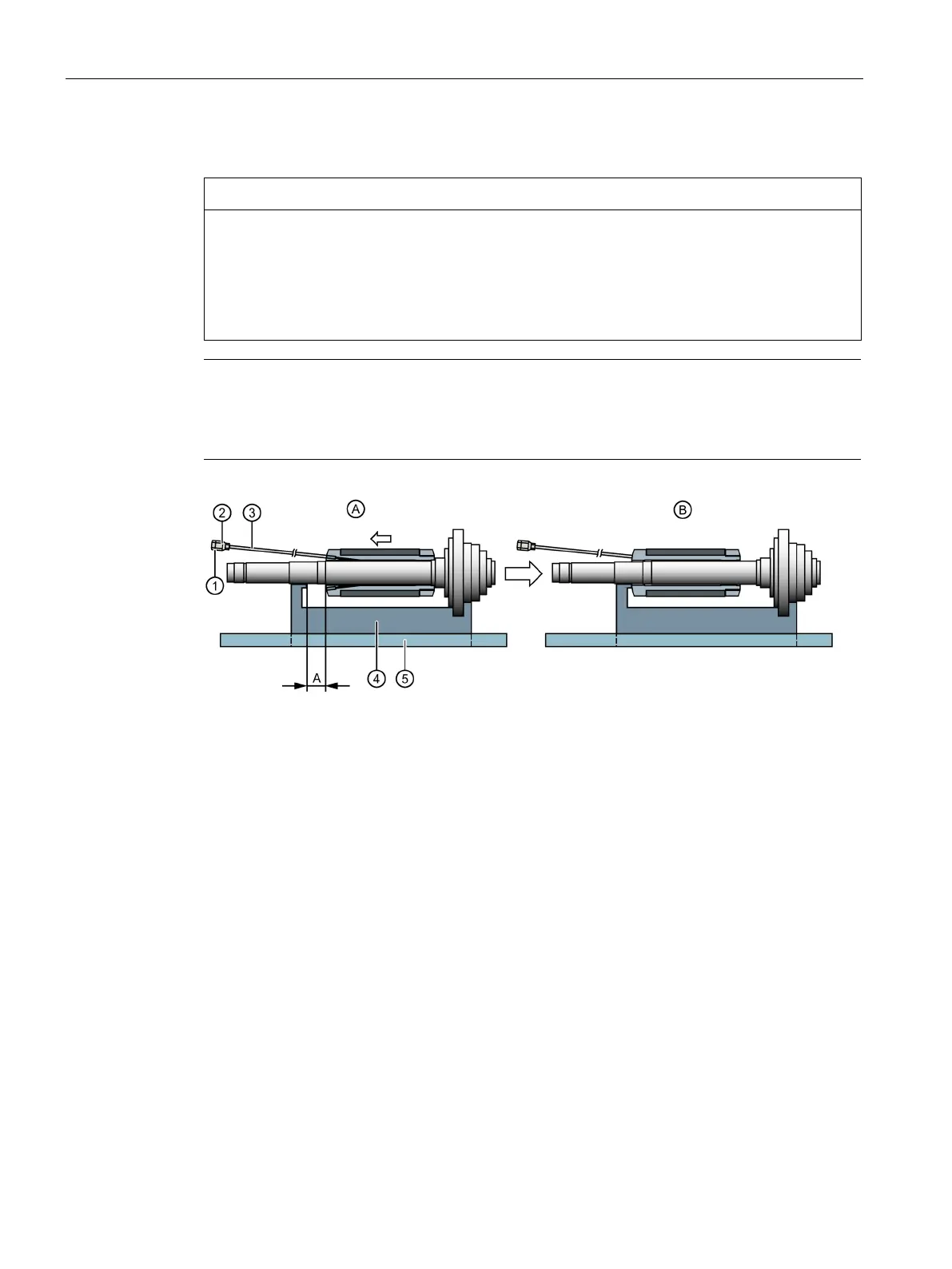
Position of rotor before release
Position of rotor after release
Connection hydraulic hand pump
Supporting fixture (prism)
1)
1)
Dimension for the relative movement = 90 mm for the synchronous version
1)
For synchronous motors made of non-magnetic material
Figure 6-15 Design of equipment for removing the rotor
1. Unscrew both grub screws from the rotor core sleeve.
2. Wrap the threaded shoulder on the extension tube
③ and the second grub screw with
Teflon sealing tape.
3. Screw the extension tube firmly into the sleeve of the rotor core.
4. Place the rotor on the prism
④.
5. Attach the oil hand pump securely to the connection
①.
6. Vent the hydraulic system.

 Loading...


