Connection
7.2 Electrical connection
SIMOTICS M-1FE2 built-in motors
148 Hardware Installation Manual, 04/2020, A5E50074509B AA
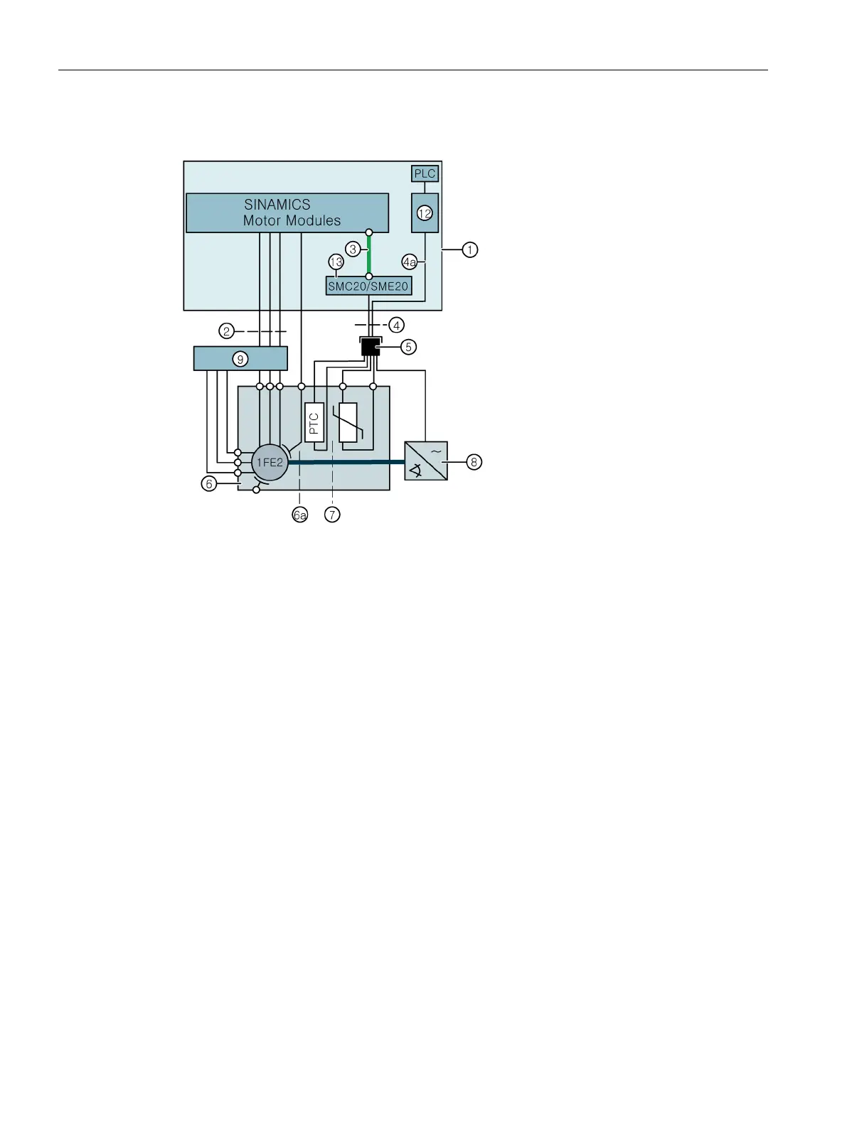
Circuit diagram for 1FE2 motor via SMC20/SME20 without VPM to SINAMICS
Not available in this circuit
Tripping unit for evaluating the PTC triplet
SMC20/SME20, encoder on the motor side, connector kits, 6FX2003-0SA12, 12-pin
DRIVE-CLiQ cable, trailable or conditionally trailable
Signal cable, trailable or only conditionally trailable, Article No.
Conductor in the signal cable from the PTC to the tripping unit
5 Signal connector, 17 pin, external thread, Article No.: 6FX2003-0SA17
Optional mounting flange for retrofitting, Article No.: 6FX2003-7DX00
Temperature sensor (+1 Pt1000 spare)
Figure 7-4 Circuit diagram for 1FE2 motor without VPM

 Loading...


