Operator control (hardware)
2.2 Operator control elements
D4x5
Manual, 05/2009
31
2.2 Operator control elements
2.2.1 Service and operating mode switch
Properties of the service and operation mode switch
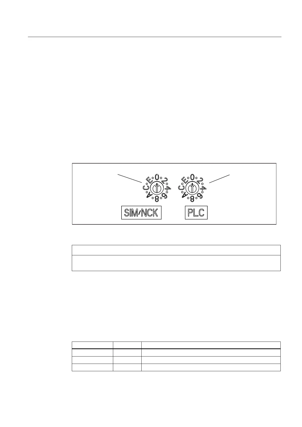
SIMOTION D4x5 has a Service selector switch and an operating mode selector switch in the
lower section of the front panel.
The switch on the right labeled PLC is used for switching the operating mode of the
SIMOTION D4x5.
The Service selector switch on the left (labeled SIM/NCK) is for service and diagnosis
functions only. In "normal" operation this switch must remain in the 0 position (see figure
below).
0RGHVHOHFWRUVZLWFK6HUYLFHVHOHFWRU
VZLWFK
Figure 2-4 Mode selector and Service selector switch SIMOTION D4x5
CAUTION
Always use an insulated screwdriver to turn the rotary switch. Otherwise, static electricity
can destroy the switch.
Mode selector switch
The following table contains the possible mode selector positions and the associated LED
displays. The mode selector positions are explained in the order in which they are arranged
on the SIMOTION D4x5.
Table 2- 1 Mode selector position
Selector position Meaning LED
0 RUN RUN
1 STOPU SU/PF
2 STOP STOP