Interfaces
3.6 PROFIBUS DP interfaces
D4x5
Manual, 05/2009
47
Interface assignments
Table 3- 11 Power supply X124
Pin Signal name Signal type Meaning
1 P24 VI Power supply 24 V
2 P24 VI 24 V power supply
3 M VO Ground
4 M VO Ground
Signal type: VI = Voltage input (power supply) VO = Voltage output (power supply)
Note
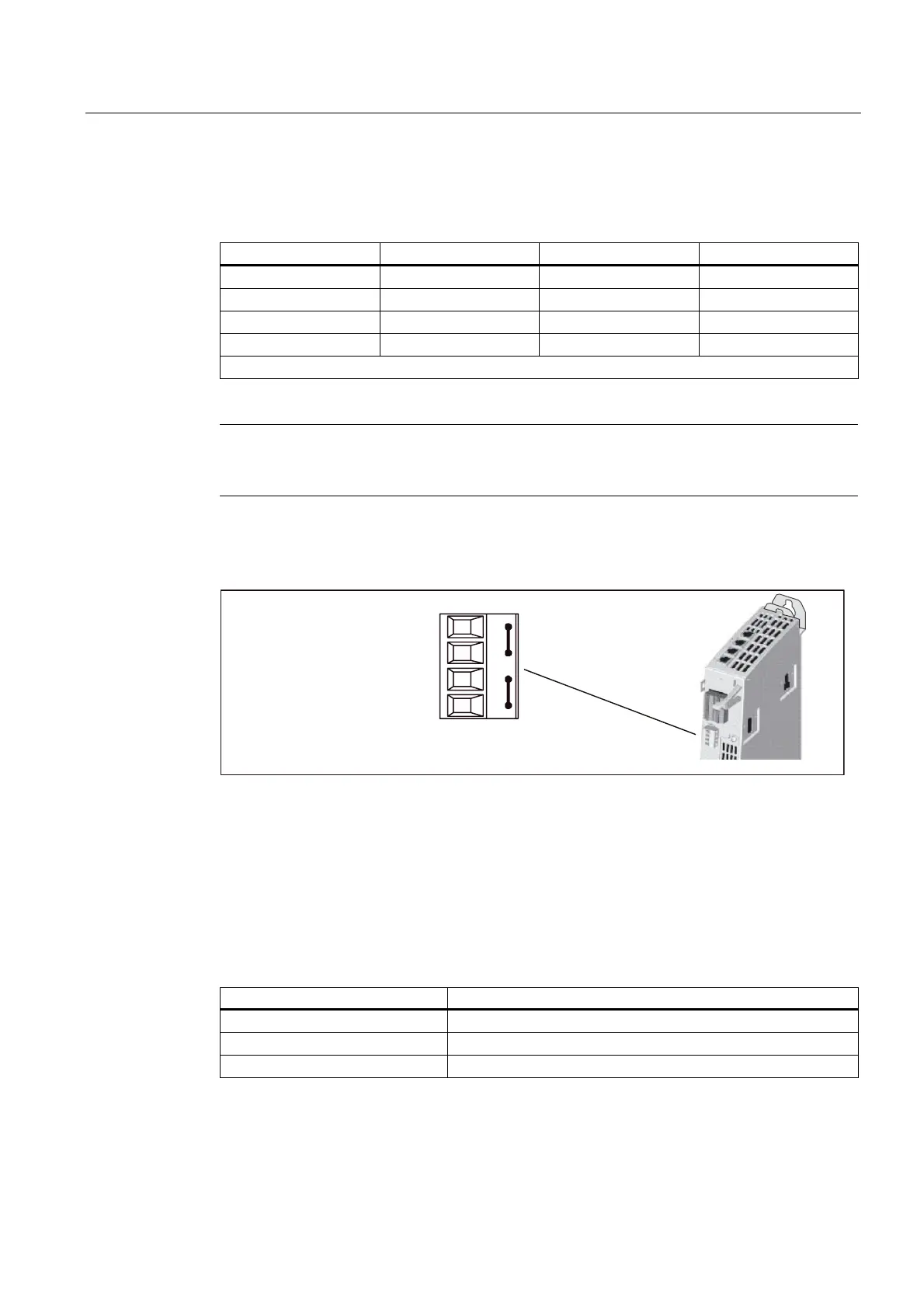
The 24 V is looped through via the 24 V connector. In this case, pin 1 is jumpered with pin 2,
and pin 3 is jumpered with pin 4.
Position of power supply interface
0
$OUHDG\SOXJJHGLQZKHQSURGXFWLVVKLSSHG
3RZHUVXSSO\FRQQHFWRU
Figure 3-5 Power supply interface
3.6 PROFIBUS DP interfaces
Features of the interface
Table 3- 12 Interfaces X126 and X136
Features Type
Connector type 9-pin SUB-D socket
Cable type PROFIBUS cable
Maximum cable length 100 m for 12 Mbits