Interfaces
3.4 Digital inputs/digital outputs
D4x5
44 Manual, 05/2009
Interface assignment of X122 and X132
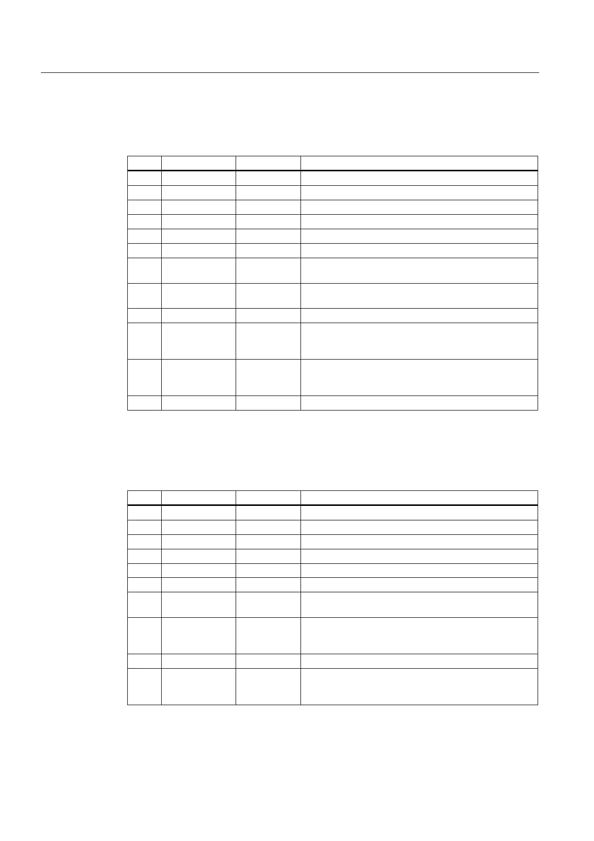
Table 3- 8 Digital inputs/outputs X122
Pin Designation
1)
Signal type
2)
Notes
1 DI0 I Digital input 0
2 DI1 I Digital input 1
3 DI2 I Digital input 2
4 DI3 I Digital input 3
5 M1 GND Ground for DI0 – DI3 (electrically isolated relative to M)
6 M GND Ground
7 DI/DO8 B Digital input/digital output 8 (can be used as a high-speed
output of an output cam/DO)
8 DI/DO9 B Digital input/digital output 9 (can be used as a high-speed
input of a measuring input or output of an output cam/DO)
9 M GND Ground
10 DI/DO10 B Digital input/digital output 10 (can be used as a high-
speed input of a measuring input or output of an output
cam/DO)
11 DI/DO11 B Digital input/digital output 11 (can be used as a high-
speed input of a measuring input or output of an output
cam/DO)
12 M GND Ground
1)
DI: digital input; DI/DO: bidirectional digital input/output; M or GND: Electronics ground;
M1: Ground reference
2)
B = Bidirectional; I = Input; GND = Reference potential (ground)
Table 3- 9 Digital inputs/outputs X132
Pin Designation
1)
Signal type
2)
Notes
1 DI4 I Digital input 4
2 DI5 I Digital input 5
3 DI6 I Digital input 6
4 DI7 I Digital input 7
5 M2 GND Ground for DI4 – DI7 (electrically isolated relative to M)
6 M GND Ground
7 DI/DO12 B Digital input/digital output 12 (can be used as a high-
speed output of an output cam/DO)
8 DI/DO13 B Digital input/digital output 13 (can be used as a high-
speed input of a measuring input or output of an output
cam/DO)
9 M GND Ground
10 DI/DO14 B Digital input/digital output 14 (can be used as a high-
speed input of a measuring input or output of an output
cam/DO)