EasyManuals Logo

Siemens SINAMICS PM240-2 User Manual

Siemens SINAMICS PM240-2
176 pages
To Next Page IconTo Next Page
To Previous Page IconTo Previous Page
Page #145 background imageLoading...
Page #145 background image
Accessories
8.9 Braking relay
Power Module PM240-2
Hardware Installation Manual, 01/2020, A5E33294624B AL
143
8.9.3 Mounting and connecting the brake relay
Installing the Brake Relay
FSA FSC: Install the Brake Relay next to the Power Module.
FSD FSG: Install the Brake Relay at the rear of the lower shield plate. Attach the
Brake Relay before you install the shield plate.
Mounting the shield plates (Page 36)
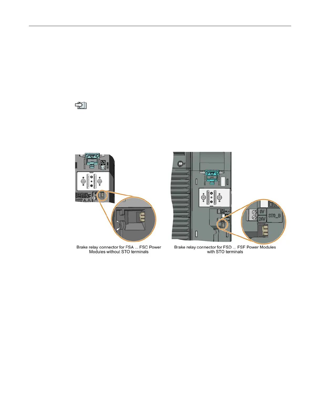
Connecting the Brake Relay to the converter
The connector for the Brake Relay is located at the front of the Power Module. Lay the cable
harness for the Brake Relay in the cable routing.

Table of Contents

Other manuals for Siemens SINAMICS PM240-2

Questions and Answers:

Question and Answer IconNeed help?

Do you have a question about the Siemens SINAMICS PM240-2 and is the answer not in the manual?

Siemens SINAMICS PM240-2 Specifications

General IconGeneral
Product type designationSINAMICS PM240-2
Protection classIP20
Input3-phase
Voltage380-480V AC
Frequency47-63Hz
Output3-phase
Communication interfacesPROFIBUS, PROFINET, USS, Modbus RTU
Braking chopperIntegrated
Relative humidity5 ... 95% (non-condensing)
Cooling methodInternal air cooling / External air cooling (depending on frame size)
Storage temperature-25 ... +70 °C

Related product manuals