Pin Protective circuit
3 On-board jumper
between 3 and 4
4
Note
Use this terminal for simple routing of the emergency stop cables, optional.
The connector is only used to assist looping through. The connected pins 1 and 2 as well as 3 and
4 have no additional function on the connection module.
X20: Enabling buttons
Connector designa‐
tion:
X20
Connector type: 8-pin Phoenix terminal
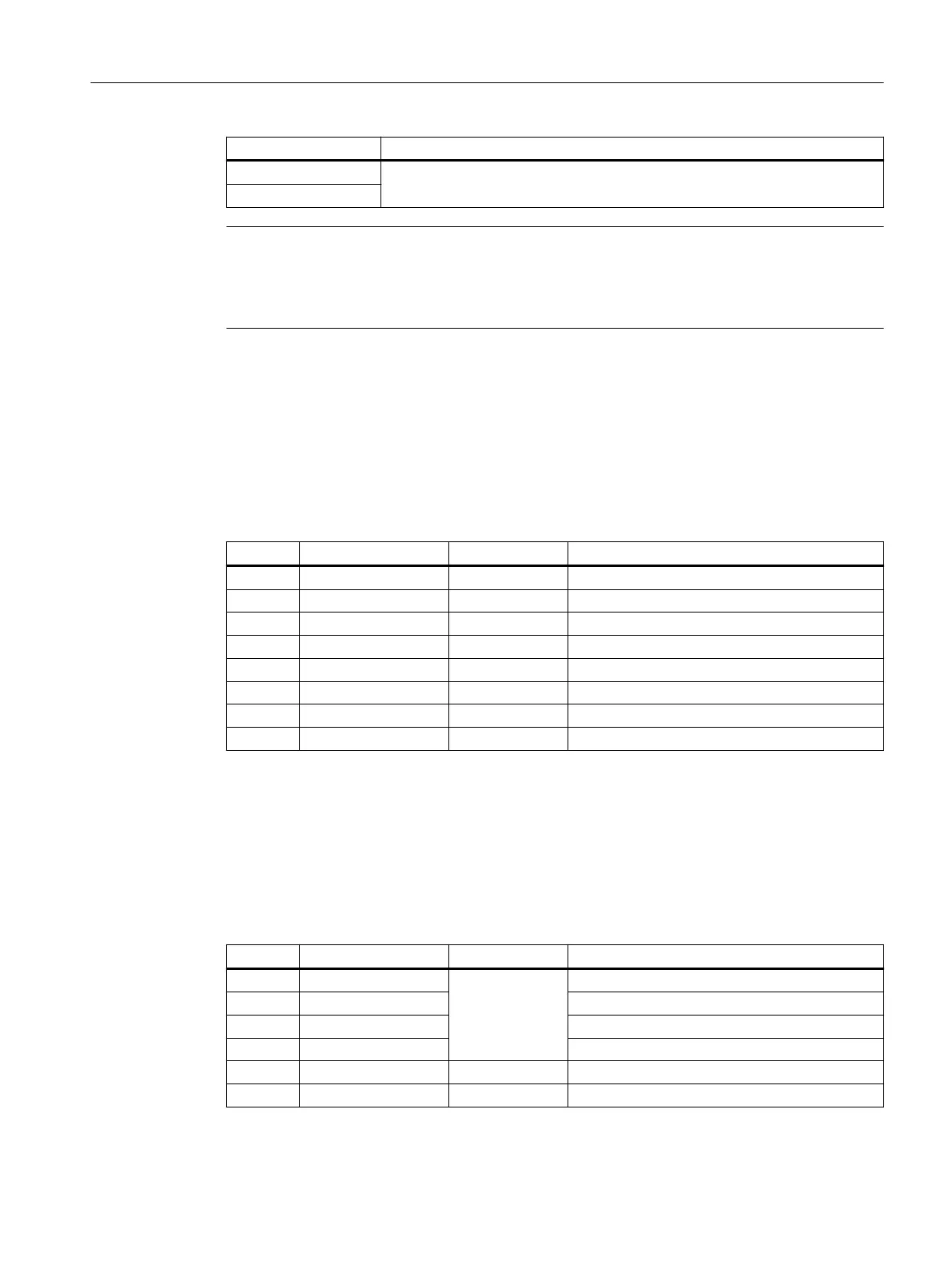
Table 7-3 Assignment of the interface enabling buttons X20
Pin Signal name Signal type Meaning
1 ZUST1P I Electronic enabling button 1 P
2 ZUST1M O Electronic enabling button 1 M
3 ZUST2P I Electronic enabling button 2 P
4 ZUST2M O Electronic enabling button 2 M
5 N.C. - Not connected
6 N.C. - Not connected
7 N.C. - Not connected
8 N.C. - Not connected
X21: Emergency Stop and key-operated switch
Connector designa‐
tion:
X21
Connector type: 10-pin Phoenix terminal
Table 7-4 Assignment of the interface Emergency Stop and Module Supply Voltage
Pin Signal name Signal type Meaning
1 STOP23
B
Emergency Stop circuit
2 STOP24 Emergency Stop circuit
3 STOP13 Emergency Stop circuit
4 STOP14 Emergency Stop circuit
5 M P Ground
6 N.C. - -
Connecting
7.3PN Basic connection module
Handheld Terminal HT 8
Equipment Manual, 02/2024, A5E52918633B AA 107
 Loading...


