+HDWGLVVLSDWLRQ
XVLQJRSHQFLUFXLWYHQWLODWLRQ
2SHUDWRU
SDQHOIURQW
+HDWGLVVLSDWLRQ
XVLQJRSHQFLUFXLWYHQWLODWLRQ
7KHUHTXLUHGYROXPHWULF
IORZIRUGLVVLSDWLQJWKHKHDW
ORVVLVFDOFXODWHGXVLQJ
DSSUR[LPDWLRQVIURP
2SHUDWRU
SDQHOIURQW
+HDWGLVVLSDWLRQ
XVLQJQDWXUDOFRQYHQWLRQDQG
LQWHUQDOWXUEXOHQFH
+HDWGLVVLSDWLRQ
XVLQJQDWXUDOFRQYHFWLRQ
7KHUHTXLUHGIUHHFRQYHFWLRQVXUIDFH$>P
@RIWKH
URRPWREHFRQYHUWHGVWHHORUDOXPLQXPVKHHWLQJPPWKLFNQHVVLVFDOFXODWHGEDVHGRQ
DWHPSHUDWXUHGLIIHUHQFH7
7
ෙ7ุ.DSSUR[LPDWHGIURP
YROXPHWULFIORZRIWKHIDQ
P
K
2SHUDWRU
SDQHOIURQW
2SHUDWRU
SDQHOIURQW
39
JHV
>:@
39
JHV
>:@39
JHV
>:@
7
7
˂7>.@
9>P
K@
7
7
˂7>.@
$>P
@
7
7
˂7>.@
$>P
@
7
7
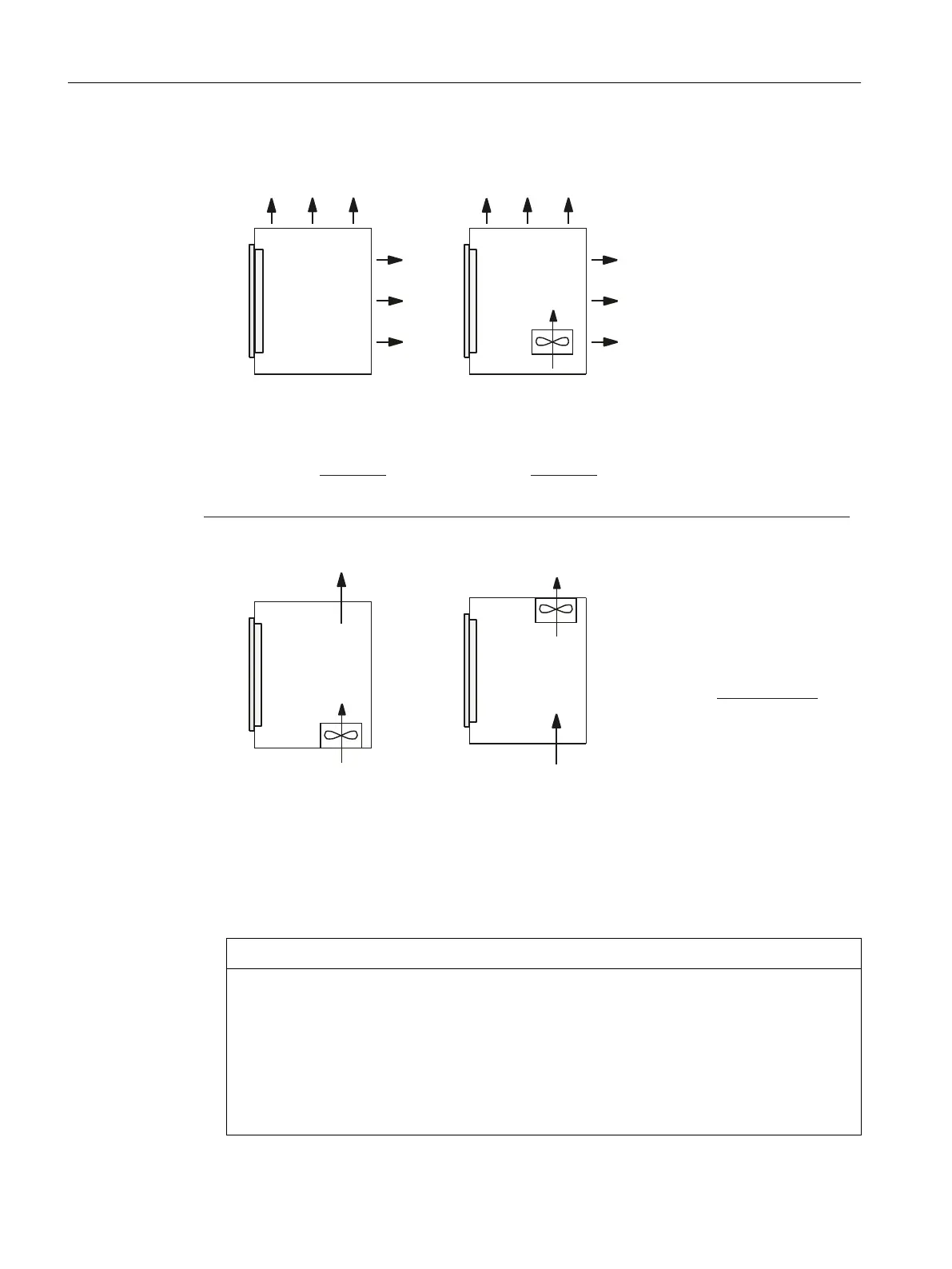
Figure4-1 Means of heat dissipation
Fan design
• The fan must be positioned to produce an optimum heat dissipation. A clearance of 10 mm
must be maintained in front of the fan.
• The inlet and outlet slots must remain free for the open-circuit ventilation.
• Air lters must be provided to maintain the permitted environmental conditions.
NOTICE
Damage to the operating components caused by temperatures that are too high or too
low
Contaminated air lters impair the desired heat dissipation. For handling the air lters, pay
attention to:
• Proper handling
• Regular replacement
• Correct disposal
General information and networking
4.1Application planning
Handheld Terminal HT 8
30 Equipment Manual, 02/2024, A5E52918633B AA
 Loading...


