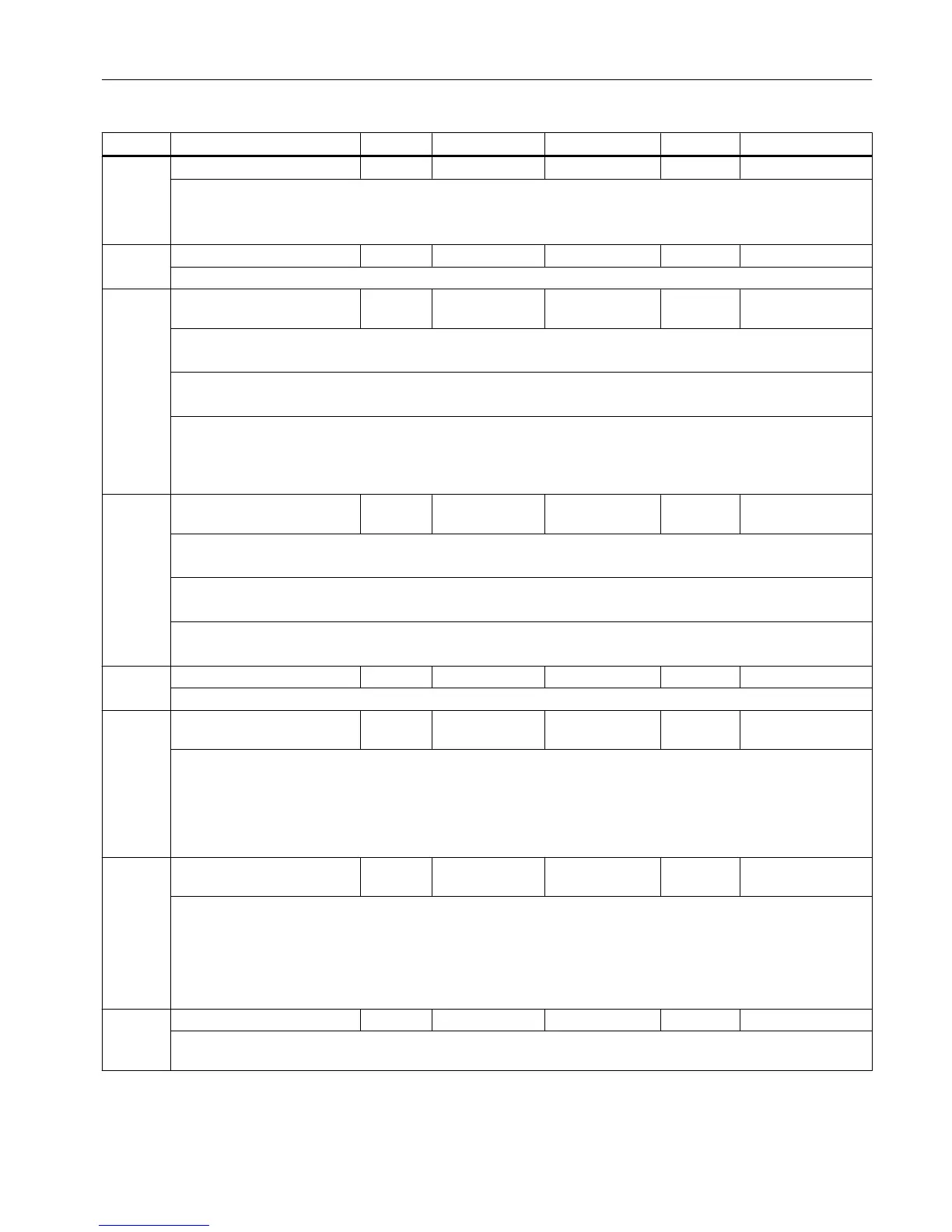
Par. No. Name Range Default Increment Unit Effective
P05 Internal enable 0-1 0 1 - Immediately
0: JOG mode can be enabled externally.
1: JOG mode can be enabled internally.
P05 automatically resets to 0 after power-on.
P16 Maximum motor current 0-100 100 1 % Power On
This parameter specifies the maximum motor current (2 x rated motor current) of your choice.
P20 * Speed loop proportional gain 0.01-5.00 Depends on
drive version
0.01 Nm*s/rad Immediately
Factory defaults:
4 Nm: 0.81 (0.54); 6 Nm: 1.19 (0.79); 7.7 Nm: 1.50 (1.00); 10 Nm: 2.10 (1.40)
Note:
Default value varies with software version.
This parameter specifies the proportional gain (K
p
, proportional component) of speed control loop.
The bigger
the value, the higher the gain and rigidity. The setting depends on specific drive and load. Generally,
the bigger the load inertia, the bigger the value is to set. If however, there is no oscillation occurred in the system,
you can set the value as big as possible.
P21 * Speed loop integral time con‐
stant
0.1-300.0 Depends on
drive version
0.1 ms Immediately
Factory defaults:
4 Nm: 17.7 (44.2); 6 Nm: 17.7 (44.2); 7.7 Nm: 17.7 (44.2); 10 Nm: 18.0 (45.0)
Note:
Default value varies with software version.
This parameter specifies the integral action time (T
n
, integral component) of speed control loop.
The smaller the value, the higher the gain and rigidity. The setting depends on specific drive and load.
P26 Maximum motor speed 0-2200 2200 20 rpm Power On
Sets the maximum possible motor speed.
P30 * Position loop proportional
gain
0.1-3.2 3.0 (2.0) 0.1 1000/min Immediately
● This parameter specifies the proportional gain of position loop.
●
The bigger the value, the higher both the gain and rigidity, and at the same pulse command frequency the
smaller the position hysteresis. However, excessively high value setting may cause system oscillation or
overshooting.
● The setting depends on specific drive and load.
P31*
Position loop feedforward
gain
0-100 85 (0) 1 % Immediately
● This parameter specifies the feedforward gain of position loop.
●
Setting the value to 100 % means position hysteresis is always 0 at any pulse command frequency.
● Increasing the feedforward gain of position loop improves the high-speed response characteristics of the
control system, but meanwhile causes the system's position loop unstable and liable to oscillation.
●
Unless very high response characteristics are necessary, set the feedforward gain of position loop to 0.
P34 Maximum following error 20-999 500 1 100 pulses Immediately
This parameter specifies the maximum possible following error. When the actual following error is larger than the
setpoint, the drive sends an over-position alarm (A43)
SINAMICS parameters
7.2 SINAMICS V60 parameters
Parameter Manual
List Manual, 01/2017 521

 Loading...


