1
10.04 Introduction
1.2 Workstation
1
Siemens AG, 2004. All rights reserved
SINUMERIK 840D/840Di/810D Operation/Programming ShopMill (BAS) – 10.04 Edition 1-23
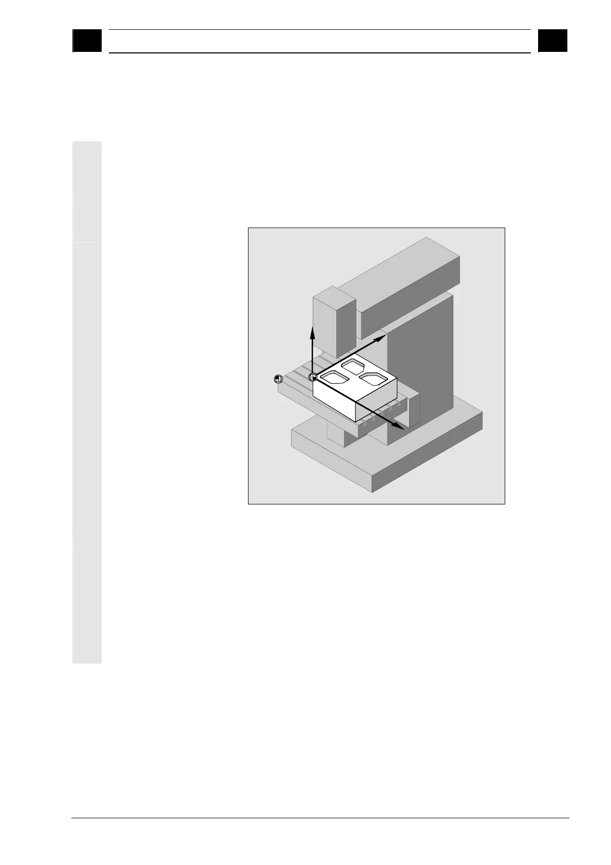
1.2.1 Coordinate system
The basic coordinate system used to machine a workpiece on a
milling machine is right-angled. It consists of the three coordinate
axes X, Y, and Z that are parallel to the machine axes.
The positions of the coordinate system and the machine zero depend
on the type of machine used.
Z
X
Y
M
W
Position of the coordinate system, machine zero and workpiece zero (example)
The axis directions are governed by the "right-hand rule" (according to
DIN 66217).
Seen from in front of the machine, the middle finger of the right hand
points in the opposite direction to the infeed of the main spindle.
Therefore:
• the thumb points in the +X direction
• the index finger points in the +Y direction
• the middle finger points in the +Z direction