9
10.04 Examples
9.3 Exam
le 3: C
linder surface transformation
9
Siemens AG, 2004. All rights reserved
SINUMERIK 840D/840Di/810D Operation/Programming ShopMill (BAS) – 10.04 Edition 9-429
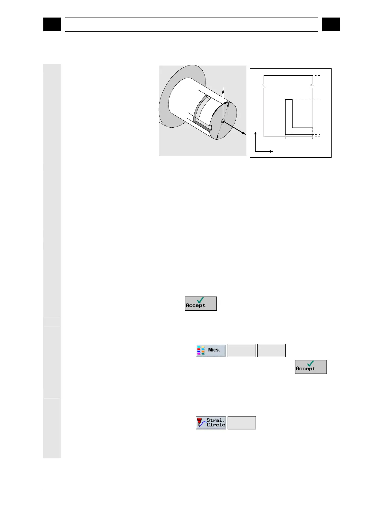
9.3 Example 3: Cylinder surface transformation
Z
Y
X
90°
10°
30°
o80mm
360
o
90
o
30
o
10
o
0
o
0-45-60-100
Y
X
Requirements
• There is a rotary axis, e.g. axis A, and the transformation is
configured via machine data.
• The reference points on the cylinder are predefined.
Program the reference points X0, Y0, Z0 and the required work
offset, for example, in "Machine Manual", "Workpiece zero" and
"Edge". The work offset calculated from these is entered in the
work offset list.
Program
1. Program header
• The blank dimensions correspond to the developed cylinder
peripheral surface (L= ∅ x π).
Define the blank:
X0 0 abs Y0 0 abs Z0 40 abs
X1 -100 abs Y1 251.327 abs Z1 20 abs RP 50
Note: Y1 is calculated from diameter 80 multiplied by π (3.14...)
• Press the
softkey.
2. Activate the work offset in
the program
Select work offset for cylinder surface transformation (e.g. offset the
zero point on the center point of the cylinder end face).
• Select via the
Transfor-
mations>
Work
offset >
softkeys
• Select the required work offset and then press the
softkey.
3. Position the Y axis Position the tool in the Y axis over the center of the cylinder since the
Y axis is not traversed after cylinder surface transformation is
selected.
• Select via the
Straight
line
softkeys
• Enter parameters: