3
Programming with ShopMill 10.04
3.8 Millin
3
Siemens AG, 2004. All rights reserved
3-274 SINUMERIK 840D/840Di/810D Operation/Programming ShopMill (BAS) – 10.04 Edition
Call help display with
the
key
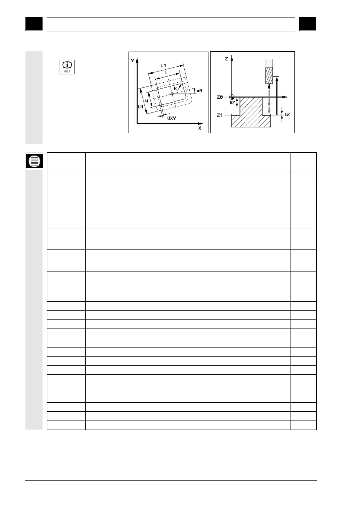
Help displays for milling rectangular spigots
Parameters Description Unit
T, F, S, V See Sec. "Programming the tool, offset value and spindle speed".
Reference
point
You can select 5 different reference points:
• Spigot center
• Bottom left
• Bottom right
• Top left
• Top right
Machining type Roughing
Finishing
Chamfer
Single pos.
Pos. pattern
rectangular spigot is machined at the programmed position (X0, Y0, Z0).
Several rectangular spigots are machined in a position pattern (e.g. full circle, pitch
circle, matrix, etc.).
X0
Y0
Z0
The positions refer to the reference point:
Position in X direction (single position only), abs. or inc.
Position in Y direction (single position only), abs. or inc.
Workpiece height (single position only), abs. or inc.
mm
mm
mm
W Width of spigot after machining mm
L Length of spigot after machining mm
R Radius at edges of spigot (corner radius) mm
α0
ngle of rotation Degr.
Z1 Depth of spigot (abs. or inc.) (not for chamfer) mm
DZ Max. depth infeed (Z direction) (not for chamfer) mm
FS
Chamfer width (for chamfer only), inc.
mm
ZFS
Insertion depth tool tip (for chamfer only), abs. or inc.
mm
UXY Finishing allowance in the plane in relation to length (L) and width (W) of the spigot;
Smaller spigot dimensions are obtained by calling the cycle again and programming
it with a lower finishing allowance.
(not for chamfer)
mm
UZ Finishing allowance in depth (tool axis) (not for chamfer) mm
W1 Width of specified blank spigot (important for determining approach position) mm
L1 Length of specified blank spigot (important for determining approach position) mm

 Loading...


