Home
Siemens
Control Unit
SINUMERIK 810D
Siemens SINUMERIK 810D Operation/Programming
5
of 3
of 3 ratings
472 pages
Give review
Manual
Specs
To Next Page
To Next Page
To Previous Page
To Previous Page
Loading...
1
10.04
Introduction
1.3 User
interface
1
ï›™
Siemens AG, 2004. All rights reserv
ed
SINUMERIK 840D/840Di/810D Operatio
n/Pr
ogramming ShopMill (BAS) – 10.
04 Edition
1-39
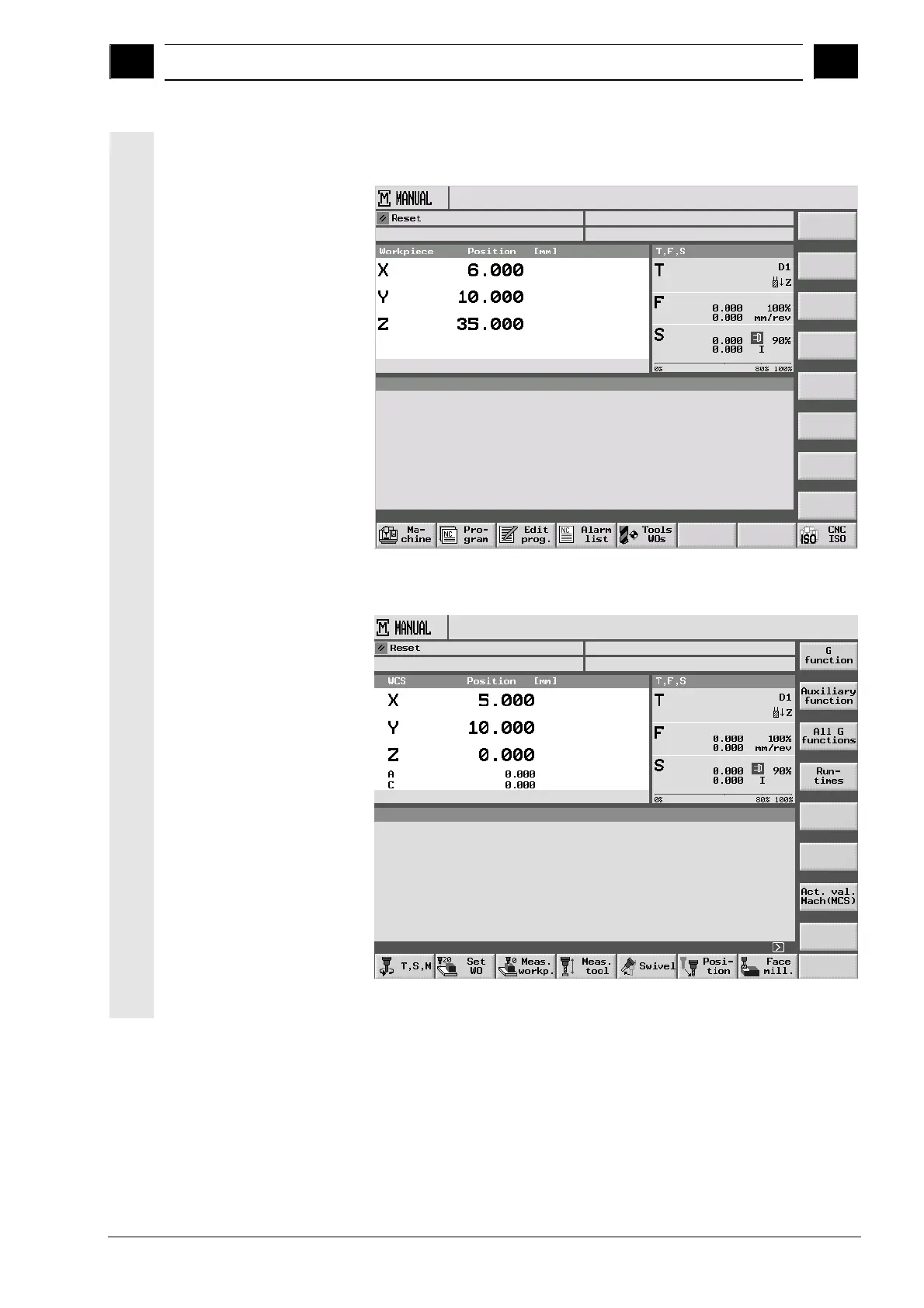
If you select another operating mode
or operating area, the horizontal
and vertical softkey bars change.
Main menu
4
Machine Manual operating mode
38
40
Table of Contents
Default Chapter
11
Table of Contents
11
Introduction
19
Shopmill
20
Sequence of Operations
21
Workstation
22
Coordinate System
23
Operator Panels
24
Operator Panel Keys
27
Machine Control Panels
29
Elements of the Machine Control Panels
29
Mini Handheld Unit
33
User Interface
35
Overview
35
Operation by Means of Softkeys and Hardkeys
38
Program Views
42
Entering Parameters
46
Fundamentals
48
Plane Designation
48
Polar Coordinates
48
Absolute Dimensions
49
Incremental Dimensions
49
Pocket Calculator Function
50
Operation
51
Switching on and off
53
Reference Point Approach
54
User Agreement in Safety Integrated
56
Operating Modes
57
Settings for the Machine
58
Switching over the Unit (Millimeter/Inch)
58
Switching over the Coordinate System (MCS/WCS)
59
Setting a New Position Value
60
Measuring Workpiece Zero
62
Measuring an Edge
66
Measuring a Corner
72
Measuring a Pocket and Hole
74
Measuring a Spigot
80
Aligning the Plane
87
Corrections after Measurement of the Zero Point
89
Calibrating an Electronic Measuring Tool
90
Measuring a Tool
92
Measuring a Tool Manually
92
Calibrating a Fixed Point
95
Measuring a Tool with Measuring Probe
96
Calibrating a Measuring Probe
99
Manual Mode
100
Selecting a Tool and Attaching It to the Spindle
100
Entering a Tool in the List and Attaching It to the Spindle
101
Entering a New Tool in the List and Loading It in the Magazine
102
Starting, Stopping, and Positioning a Spindle Manually
102
Traversing Axes
104
Positioning Axes
106
Swiveling
106
Face Milling
110
Settings for Manual Mode
111
MDI Mode
114
Automatic Mode
115
Switchover between "T, F, S", "G Functions" and "Auxiliary Functions" Displays
116
Selecting a Program for Execution
117
Starting/Stopping/Aborting a Program
118
Interrupting a Program
119
Starting Execution at a Specific Point in the Program
120
Controlling the Program Run
125
Overstore
127
Testing a Program
128
Simultaneous Recording before Machining
129
Simultaneous Recording During Machining
131
Trial Program Run
132
Single Block
132
Displaying the Current Program Block
133
Correcting a Program
134
Run Times
135
Tools and Tool Offsets
136
Creating a New Tool
143
Setting up more than One Edge Per Tool
145
Changing the Tool Name
146
Creating a Replacement Tool
146
Manual Tools
146
Tool Offsets
147
Miscellaneous Functions for a Tool
150
Entering Tool Wear Data
151
Activating Tool Monitoring
152
Magazine List
154
Deleting a Tool
155
Changing the Tool Type
155
Loading/Unloading a Tool Into/Out of the Magazine
156
Relocating a Tool
158
Positioning a Location
160
Sorting Tools
160
Work Offsets
161
Defining Work Offsets
163
Work Offset List
164
Selecting/Deselecting the Work Offset in the Manual Area
166
Switching to CNC-ISO Mode
167
Shopmill Open (PCU 50)
168
Remote Diagnostics
168
Programming with Shopmill
169
Basics of Programming
171
Program Structure
174
Creating a Sequential Control Program
175
Creating a New Program; Defining a Blank
175
Programming New Blocks
179
Changing Program Blocks
181
Program Editor
182
Programming the Tool, Offset Value and Spindle Speed
185
Contour Milling
186
Representation of the Contour
189
Creating a New Contour
191
Creating Contour Elements
193
Changing a Contour
198
Programming Examples for Freely Defined Contours
200
Path Milling
203
Predrilling a Contour Pocket
206
Milling a Contour Pocket (Roughing)
209
Removing Residual Material from a Contour Pocket
210
Finishing the Contour Pocket
212
Chamfering a Contour Pocket
215
Milling Contour Spigots (Roughing)
216
Removing Residual Material from a Contour Spigot
217
Finishing the Contour Spigot
219
Chamfering a Contour Spigot
220
Linear or Circular Path Motions
221
Straight
221
Circle with Known Center Point
223
Circle with Known Radius
224
Helix
225
Polar Coordinates
226
Straight Polar
227
Circle Polar
228
Programming Examples for Polar Coordinates
229
Drilling
230
Centering
231
Drilling and Reaming
232
Deep-Hole Drilling
233
Boring
235
Tapping
236
Thread Milling
238
Drill and Thread Milling
242
Positioning on Freely Programmable Positions and Position Patterns
245
Freely Programmable Positions
245
Freely Programmable Positions
246
Line Position Pattern
250
Matrix Position Pattern
251
Box Position Pattern
252
Full Circle Position Pattern
253
Pitch Circle Position Pattern
255
Including and Skipping Positions
257
Obstacle
258
Repeating Positions
260
Programming Examples for Drilling
261
Milling
263
Face Milling
263
Rectangular Pocket
266
Circular Pocket
270
Rectangular Spigot
272
Circular Spigot
275
Longitudinal Slot
277
Circumferential Slot
280
Use of Position Patterns for Milling
283
Engraving
286
Measurement
291
Measuring the Workpiece Zero
291
Measuring the Tool
293
Calibrating the Measuring Calipers
295
Miscellaneous Functions
296
Calling a Subroutine
296
Repeating Program Blocks
298
Changing Program Settings
300
Calling Work Offsets
301
Defining Coordinate Transformations
302
Cylinder Surface Transformation
305
Swiveling
309
Miscellaneous Functions
309
Inserting G Code into the Sequential Control Program
314
Programming with G Code
318
Creating a G Code Program
318
Running a G Code Program
321
G Code Editor
323
Arithmetic Variables
327
ISO Dialects
328
Simulation
329
General Information
330
Starting/Stopping a Program in Standard Simulation
331
Representation as a Plan View
333
Representation as a 3-Plane View
334
Enlarging a Portion of the Display
335
Three-Dimensional Display
336
Changing the Position of the Viewport
337
Cutting a Section out of the Workpiece
338
Starting/Stopping the Quick Display for Mold Making
339
Views in the Quick Display
339
Zooming and Panning the Workpiece Graphics
341
Distance Measurement
342
Search Function
343
Editing Part Program Blocks
344
Selecting G Blocks
344
Editing a G Code Program
345
File Management
347
Program Management with Shopmill
348
Program Management with PCU 20
349
Opening a Program
351
Executing a Program
352
Multiple Clamping
352
Running a G Code Program from Floppy Disk or Network Drive
355
Creating a Directory/Program
356
Selecting Multiple Programs
357
Copying/Renaming a Directory or Program
358
Deleting a Directory/Program
359
Running a Program Via the RS-232 Interface
360
Importing/Exporting a Program Via the RS-232 Interface
361
Displaying the Error Log
363
Backing Up/Importing Tool or Zero Point Data
363
Program Management with PCU 50
363
Program Management with PCU 50
364
Opening a Program
368
Executing a Program
369
Multiple Clamping
370
Loading/Unloading a Program
372
Executing a G Code Program from the Hard Disk, Floppy Disk or Network Drive
373
Creating a Directory/Program
375
Selecting Multiple Programs
376
Copying/Renaming/Moving Directories/Programs
377
Deleting a Directory/Program
379
Importing/Exporting a Program Via the RS-232 Interface
380
Displaying the Error Log
382
Backing Up/Importing Tool or Zero Point Data
382
Mold Making
385
Requirements
386
Setting up the Machine
388
Measuring the Tool
388
Creating a Program
389
Programming a Tool
389
Programming the "High Speed Settings" Cycle
389
Subroutine Call
390
Executing a Program
391
Selecting a Program for Execution
391
Starting Execution at a Specific Point in the Program
391
Example
393
Alarms and Messages
397
Cycle Alarms and Messages
398
Error Handling in the Cycles
398
Overview of Cycle Alarms
398
Messages in the Cycles
403
Alarms in Shopmill
404
Overview of Alarms
404
Selecting the Alarm/Message Overview
405
Description of the Alarms
406
User Data
415
Version Display
416
Examples
418
Example 1: Machining with Rectang./Circ. Pocket and Circumf. Slot
418
Example 2: Translation and Mirroring of a Contour
426
Example 3: Cylinder Surface Transformation
429
Example 4: Slot Side Compensation
433
Example 5: Swiveling
437
Appendix
445
A Abbreviations
445
B References
445
C Index
445
Other manuals for Siemens SINUMERIK 810D
Operator's Guide
520 pages
Programming Guide
598 pages
Commissioning Manual
626 pages
Programming Manual
687 pages
Diagnostic Manual
880 pages
Diagnostics Guide
622 pages
Function Manual
2184 pages
Configuration Manual
148 pages
Installation And Startup Guide
327 pages
Operation & Programming Manual
233 pages
Start-Up And Upgrade Guide
8 pages
5
Based on 3 ratings
Ask a question
Give review
Questions and Answers:
Need help?
Do you have a question about the Siemens SINUMERIK 810D and is the answer not in the manual?
Ask a question
Siemens SINUMERIK 810D Specifications
General
Brand
Siemens
Model
SINUMERIK 810D
Category
Control Unit
Language
English
Related product manuals
Siemens SINUMERIK 840D
713 pages
Siemens SINUMERIK 808D
48 pages
Siemens SINUMERIK 840C
291 pages
Siemens SINUMERIK 802D
399 pages
Siemens SINUMERIK 840Di
552 pages
Siemens Sinumerik 840 sl
520 pages
Siemens SINUMERIK 840Dsl
74 pages
Siemens SINUMERIK 880 GA2
291 pages
Siemens SINUMERIK 840Di sl
470 pages
Siemens Sinumerik 840DiE sl
545 pages
Siemens SINUMERIK 808D ADVANCED
498 pages
SINUMERIK 840D Simodrive 611 digital
298 pages