2
Operation 10.04
2.6 Measurin
work
iece zero
2
Siemens AG, 2004. All rights reserved
2-82 SINUMERIK 840D/840Di/810D Operation/Programming ShopMill (BAS) – 10.04 Edition
Measuring a rectangular
spigot automatically
1. Attach a 3D probe type tool to the spindle.
2. Move the tool until it is approximately at the center of the spigot.
3. Prepare the measurement (as described under "Measuring a
rectangular spigot manually", steps 2 to 6).
4. Enter the infeed value in "DZ" to determine the measuring depth.
5. In field "L" enter the length (1st axis of the working plane) and in
"W" (2nd axis of the working plane) enter the width of the spigot, if
the measuring stroke would not reach the edges.
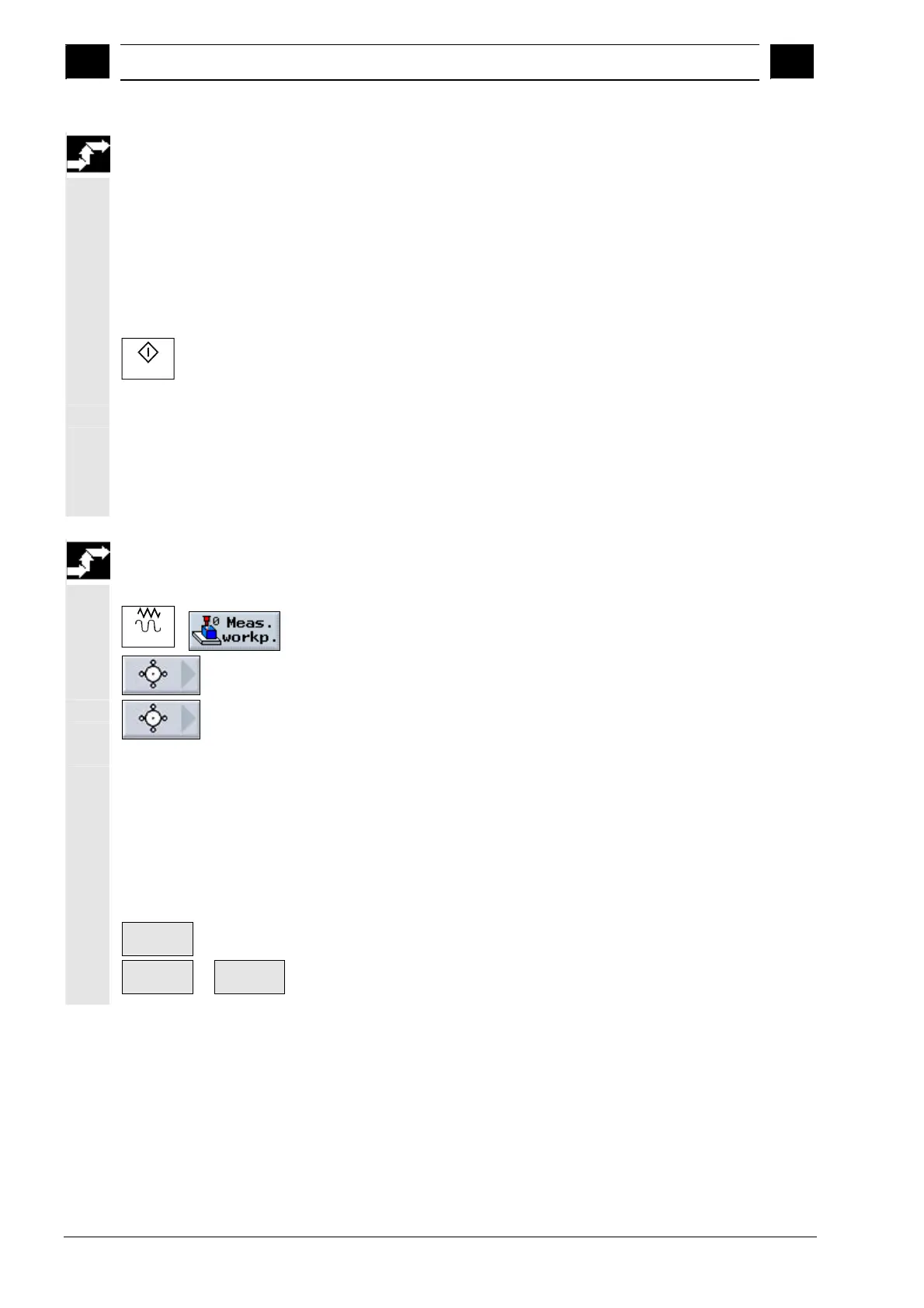
Cycle Start
6. Press the "Cycle Start" key.
The tool automatically contacts 4 points in succession around the
outside wall of the spigot.
The length, width, and center point of the rectangular spigot are
calculated and displayed.
The set position of the center point is stored as the new zero point if
you have selected "work offset". The tool radius is automatically
included in the calculation.
Measuring a circular
spigot manually
1. Attach any tool for scratching to the spindle.
Jog
2. In "Machine Manual" mode, select the "Meas. workp." softkey.
3. Press the "Spigot" softkey.
4. Press the "1 circular spigot" softkey.
5. Specify whether you want "Measurement only" or in which work
offset you want to store the zero point (as described under
"Measuring an edge manually", step 5).
6. Enter the infeed value in "DZ" to determine the measuring depth.
7. Specify the position setpoints (X0 and Y0) of the spigot center
point P0.
8. Traverse the tool to the first measuring point on the spigot outside
wall.
Save P1
9. Press the "Save P1" softkey.
Save P2
...
Save P4
10. Repeat steps 8 and 9 to measure and store measuring points P2,
P3, and P4.