12.95
3.2 Installing the SINUMERIK 810D
3-45
E Siemens AG, 2002. All rights reserved
SINUMERIK 810D Manual Hardware Configuration (PHC) -- 11.02 Edition
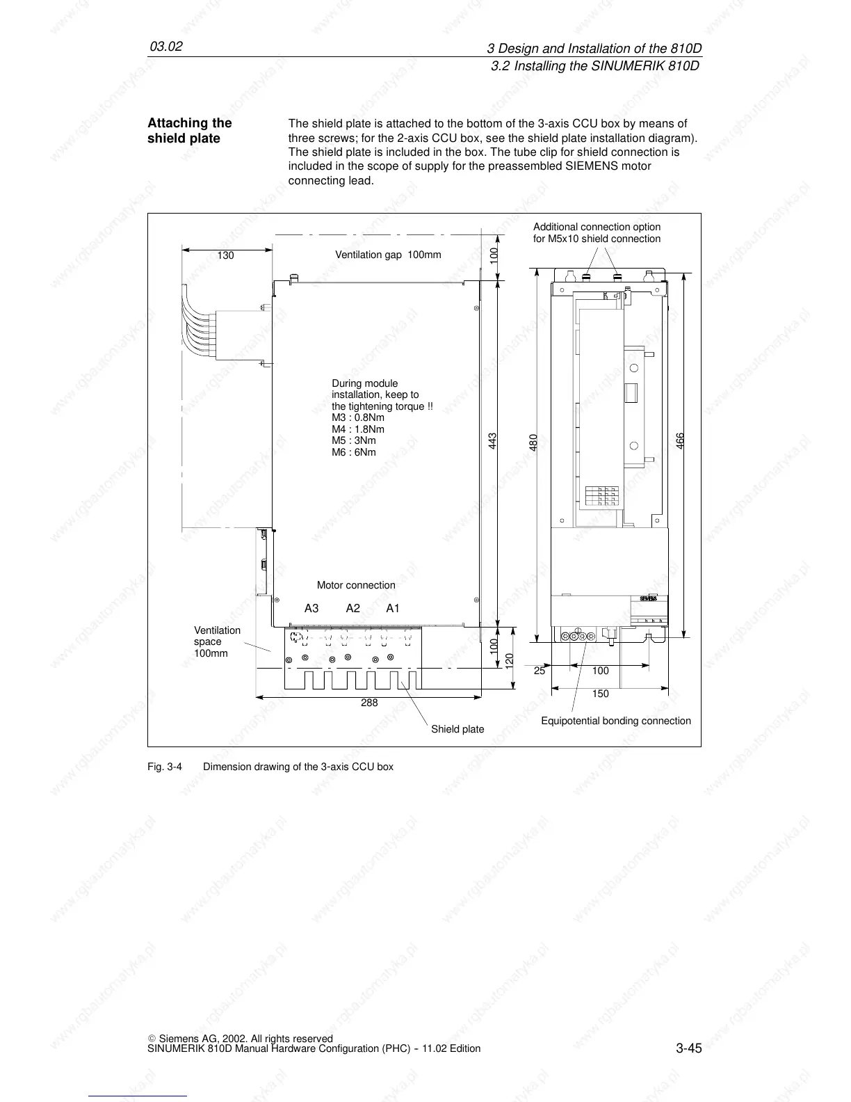
The shield plate is attached to the bottom of the 3-axis CCU box by means of
three screws; for the 2-axis CCU box, see the shield plate installation diagram).
The shield plate is included in the box. The tube clip for shield connection is
included in the scope of supply for the preassembled SIEMENS motor
connecting lead.
480
443
150
10025
466
Additional connection option
for M5x10 shield connection
During module
installation, keep to
the tightening torque !!
M3 : 0.8Nm
M4 : 1.8Nm
M5 : 3Nm
M6 : 6Nm
100
Ventilation
space
100mm
Shield plate
100
Ventilation gap 100mm
130
288
Equipotential bonding connection
120
A3 A2 A1
Motor connection
Fig. 3-4 Dimension drawing of the 3-axis CCU box
Attaching the
shield plate
 Loading...


